
Polishing apparatus

A technology for equipment and polishing surfaces, used in grinding/polishing equipment, metal processing equipment, machine tools for surface polishing, etc., which can solve problems such as production reduction

Active Publication Date: 2008-09-03
EBARA CORP
View PDF0 Cites 39 Cited by
  • Summary
  • Abstract
  • Description
  • Claims
  • Application Information

AI Technical Summary

Problems solved by technology

However, additional work is required to mount and remove the dummy wafer from the polishing head or top ring, and this extra work is responsible for the reduced yield

Method used


Image

  • Polishing apparatus
  • Polishing apparatus
  • Polishing apparatus

Examples


Embodiment Construction

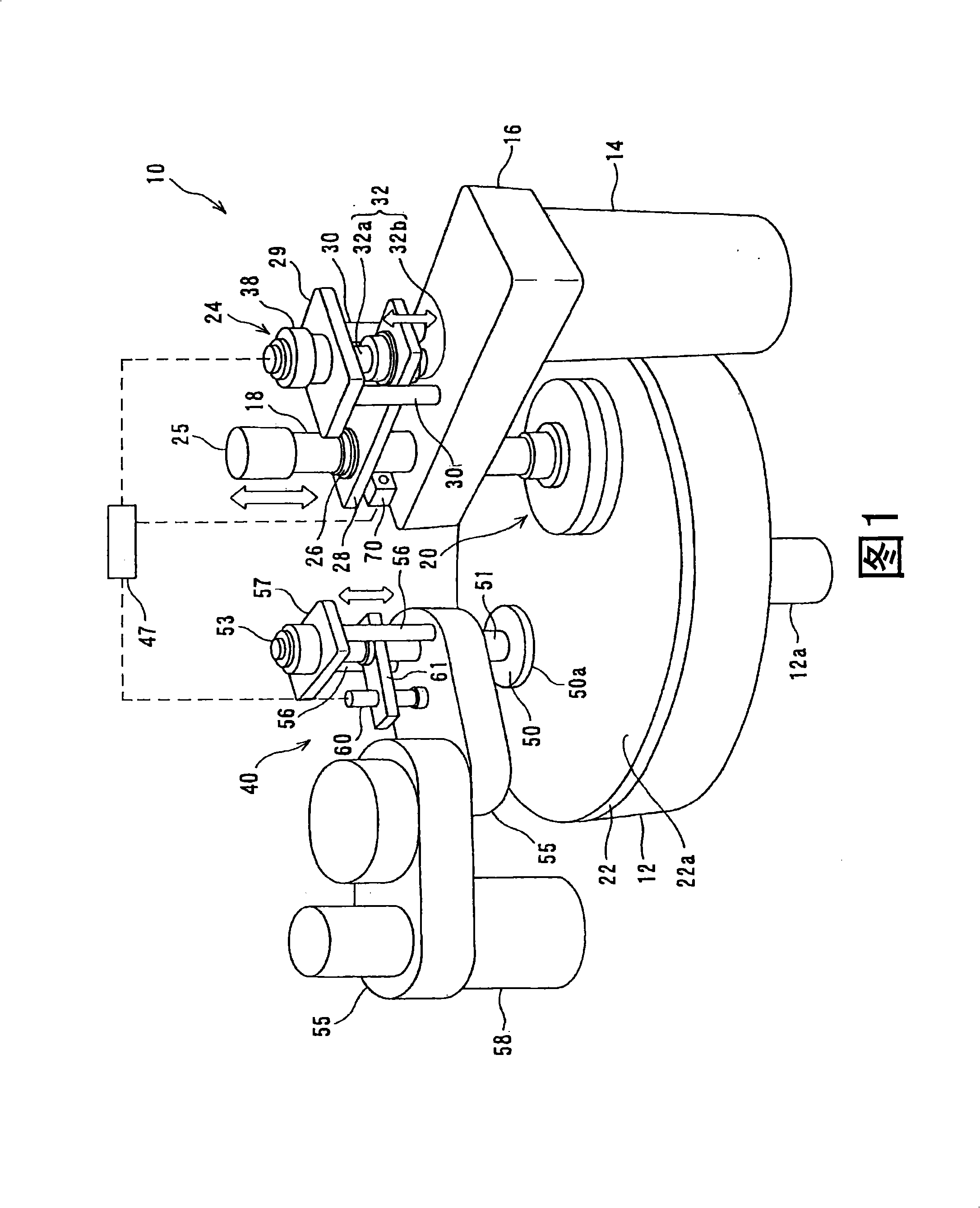
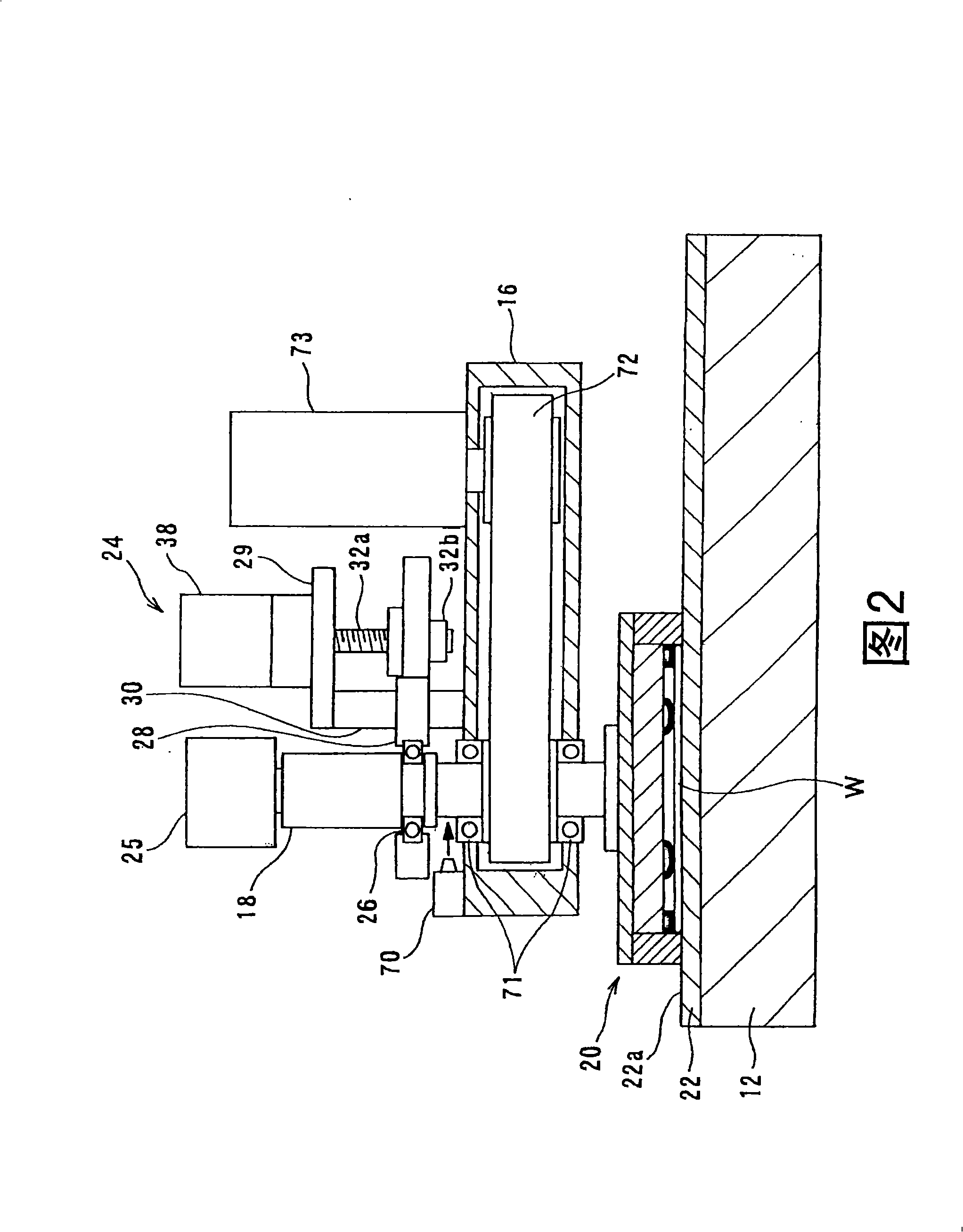
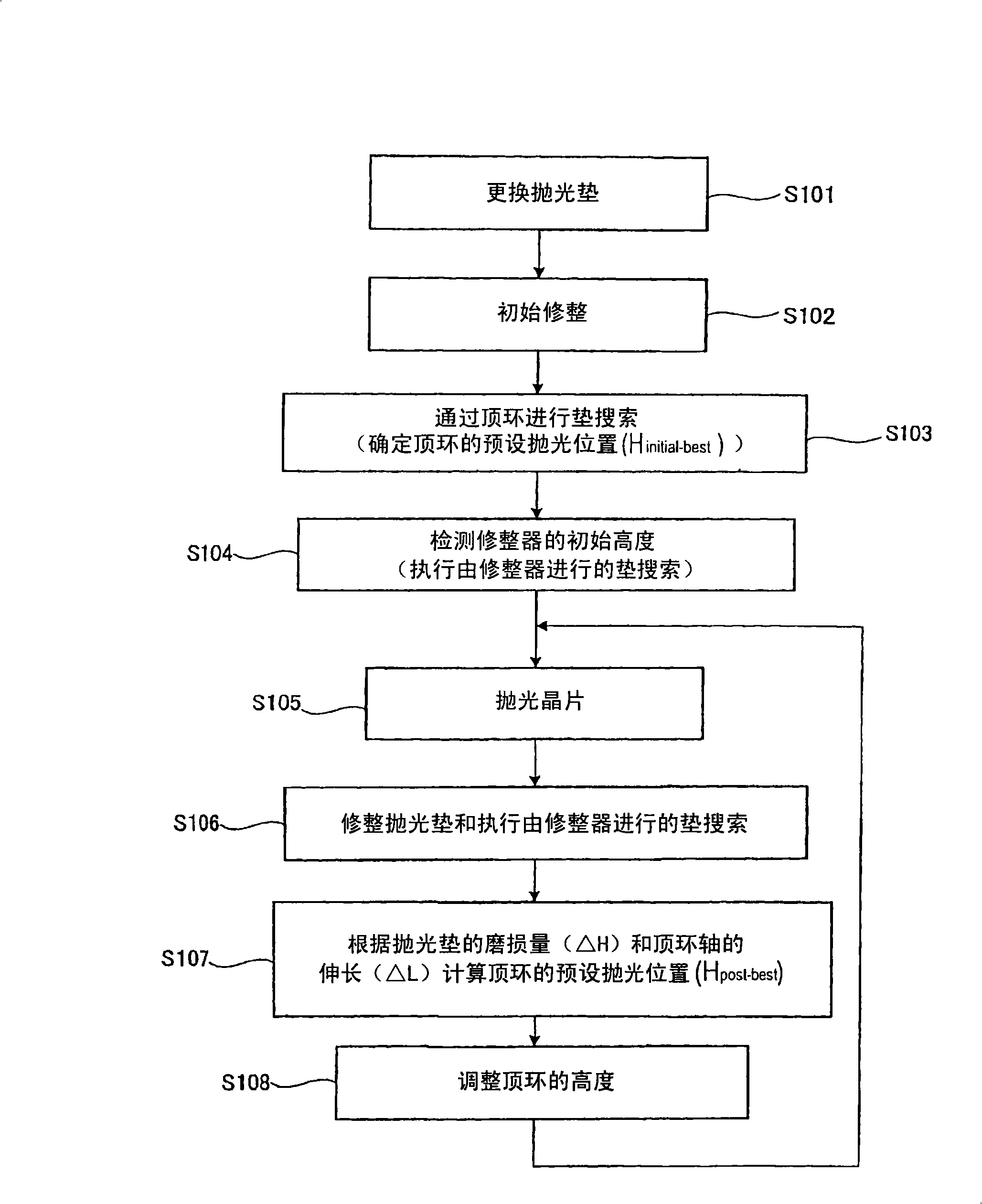
[0078] Referring to Figs. 1 to 18, an embodiment of the polishing apparatus of the present invention will be described below. In all the drawings, similar or identical components are denoted by similar or identical reference numerals, and they will not be described repeatedly in the following.

[0079] FIG. 1 is a schematic diagram showing a polishing apparatus 10 of a first embodiment of the present invention. As shown in Figure 1, polishing equipment 10 has polishing table 12, is connected to the top ring head 16 of supporting shaft 14 upper ends, is installed in the top ring shaft 18 on top ring head 16 free ends, is connected to the top ring of top ring shaft 18 bottoms 20. In the illustrated embodiment, the top ring 20 is a substantially circular plate. The top ring shaft 18 is connected to the top ring rotating motor through connecting means such as a timing belt, so that the top ring shaft 18 can rotate. However, in FIG. 1, the top ring rotating motor, the timing bel...


PUM


Abstract

A polishing apparatus is used for polishing a substrate such as a semiconductor wafer to a flat mirror finish. The polishing apparatus includes a polishing table having a polishing surface, a top ring configured to hold and press the substrate against the polishing surface, a top ring shaft configured to lift and lower the top ring, and an elongation detecting device configured to detect an elongation of the top ring shaft. The polishing apparatus further includes a controller configured to set a vertical position of the top ring at the time of polishing, and control a lifting and lowering mechanism to lower the top ring to a preset polishing position as the set vertical position. The controller corrects the preset polishing position based on the elongation of the top ring shaft which has been detected by the elongation detecting device.

Description

technical field [0001] The present invention relates to a polishing apparatus, and more particularly to a polishing apparatus for polishing an object (substrate) to be polished, such as a semiconductor wafer, to a mirror finish. Background technique [0002] In recent years, high integration and high density in semiconductor devices have required smaller and smaller wiring forms or interconnections, and also required more and more interconnection layers. Multilevel interconnects in smaller circuits result in more steps that cause surface irregularities in the underlying interconnect layers. The increase in the number of interconnection layers leads to poor film coating (step coverage) performance on the film step structure. Therefore, better multilayer interconnection requires improved step coverage and proper surface planarization. In addition, since the depth of focus of the photolithography optical system is made smaller by miniaturization of the photolithography proces...

Claims


Application Information

Patent Timeline
Patent Type & Authority Applications(China)
IPC IPC(8): B24B29/00H01L21/304B24B49/04B24B53/12B24B37/07B24B37/10B24B49/10B24B53/02
CPCB24B49/14B24B49/18B24B53/017H01L21/304
Inventor 齐藤贤一郎锅谷治永田公秀户川哲二
Owner EBARA CORP
Learn More