Precision measurement method for flat crack and antenna crack
A crack antenna and precision measurement technology, which is applied in the direction of measurement devices, optical testing flaws/defects, image data processing, etc., can solve the problems of slow measurement speed, high price, high cost, etc., to improve measurement accuracy, shorten detection time, and automate high degree of effect
- Summary
- Abstract
- Description
- Claims
- Application Information
AI Technical Summary
Problems solved by technology
Method used
Image

Examples
Embodiment Construction
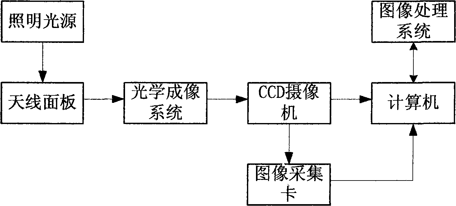
[0039] Such as figure 1 As shown, an image extraction device such as a CCD camera is electrically connected to an image acquisition card connected to a computer interface, and the CCD camera transmits and converts image data to be read by the computer through image acquisition. The image information obtained by the computer is expressed in units of pixels. If the actual measurement result value is to be given, the corresponding relationship between the digital image pixel and the actual size must be established. It is necessary to convert the CCD image coordinates to the workbench coordinates, so before the measurement, it is necessary to calibrate the conversion coefficient K from the CCD coordinate system to the workbench coordinate system. Calibration is actually to determine the actual physical size represented by each pixel. Whether the calibration is accurate or not will directly affect the measurement accuracy of the image measurement system.
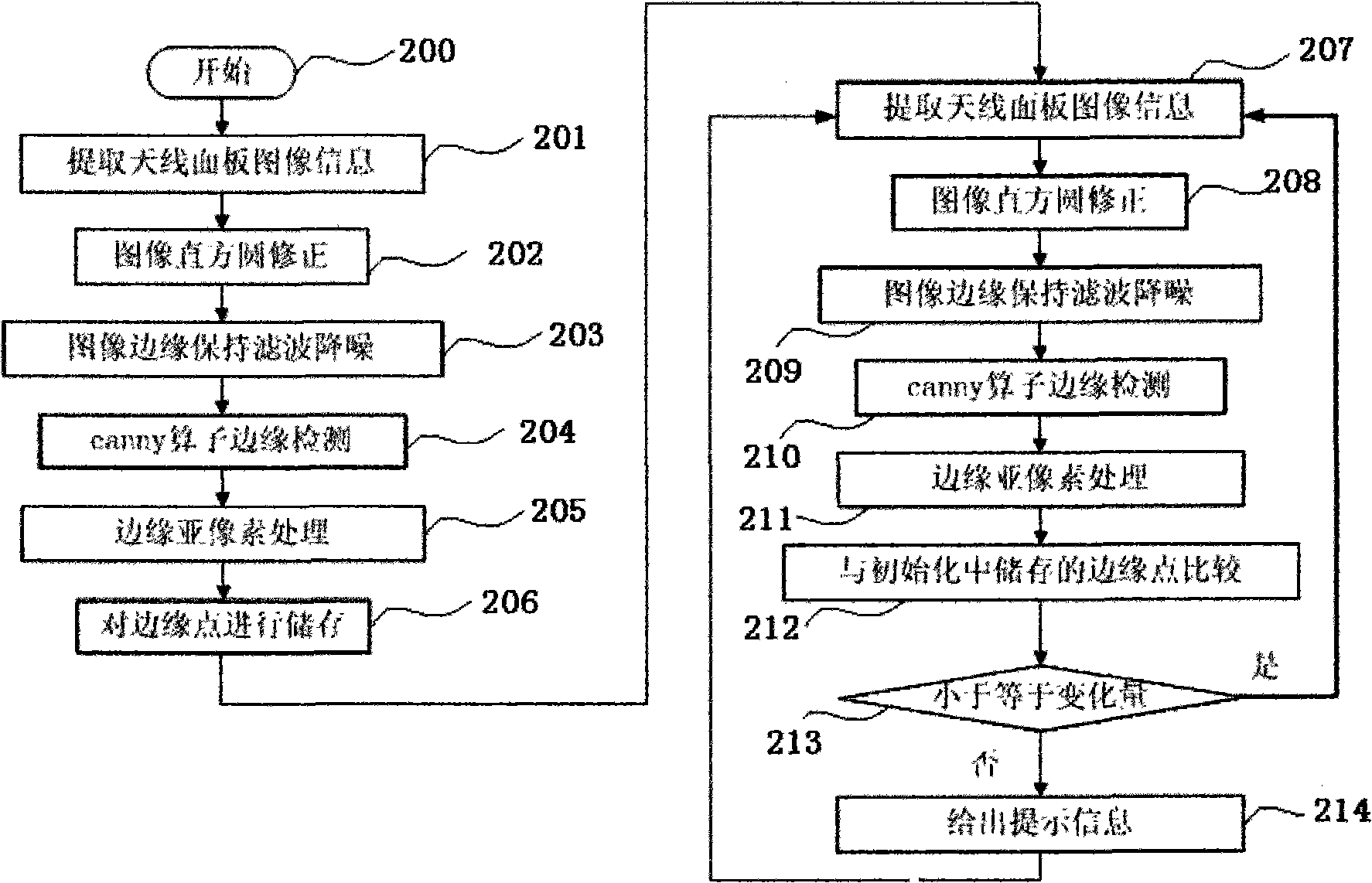
[0040] figure 2 Provi...
PUM
 Abstract
Description
Claims
Application Information
PatSnap Eureka turns technology decisions into work you can execute. Powered by our Innovation Knowledge Graph, it runs expert workflows across engineering, life sciences, materials and intellectual property. Get your review-ready output in minutes.


