
Fuel cell and method for connecting current connectors thereto

A fuel cell and current collector technology, applied to fuel cell parts, fuel cells, solid electrolyte fuel cells, etc., can solve problems such as short circuit of electrodes, elongated terminals of current collectors, increased resistance, etc., to reduce area effect

Inactive Publication Date: 2008-09-03
SANYO ELECTRIC CO LTD
View PDF1 Cites 2 Cited by
  • Summary
  • Abstract
  • Description
  • Claims
  • Application Information

AI Technical Summary

Problems solved by technology

Therefore, it is necessary to increase the area of ​​the current collector more than necessary while at the same time the terminal of the current collector becomes longer, resulting in an increase in resistance
[0006] In addition, as described in Patent Document 1, there is also known a structure in which through-holes and connectors are provided in the electrolyte membrane between adjacent single cells. In the case of this, there is a problem that adjacent electrodes are short-circuited or cross leakage occurs in the through-hole portion.

Method used


Image

  • Fuel cell and method for connecting current connectors thereto
  • Fuel cell and method for connecting current connectors thereto
  • Fuel cell and method for connecting current connectors thereto

Examples


Embodiment Construction

[0028] Embodiments of the present invention will be described below with reference to the drawings.

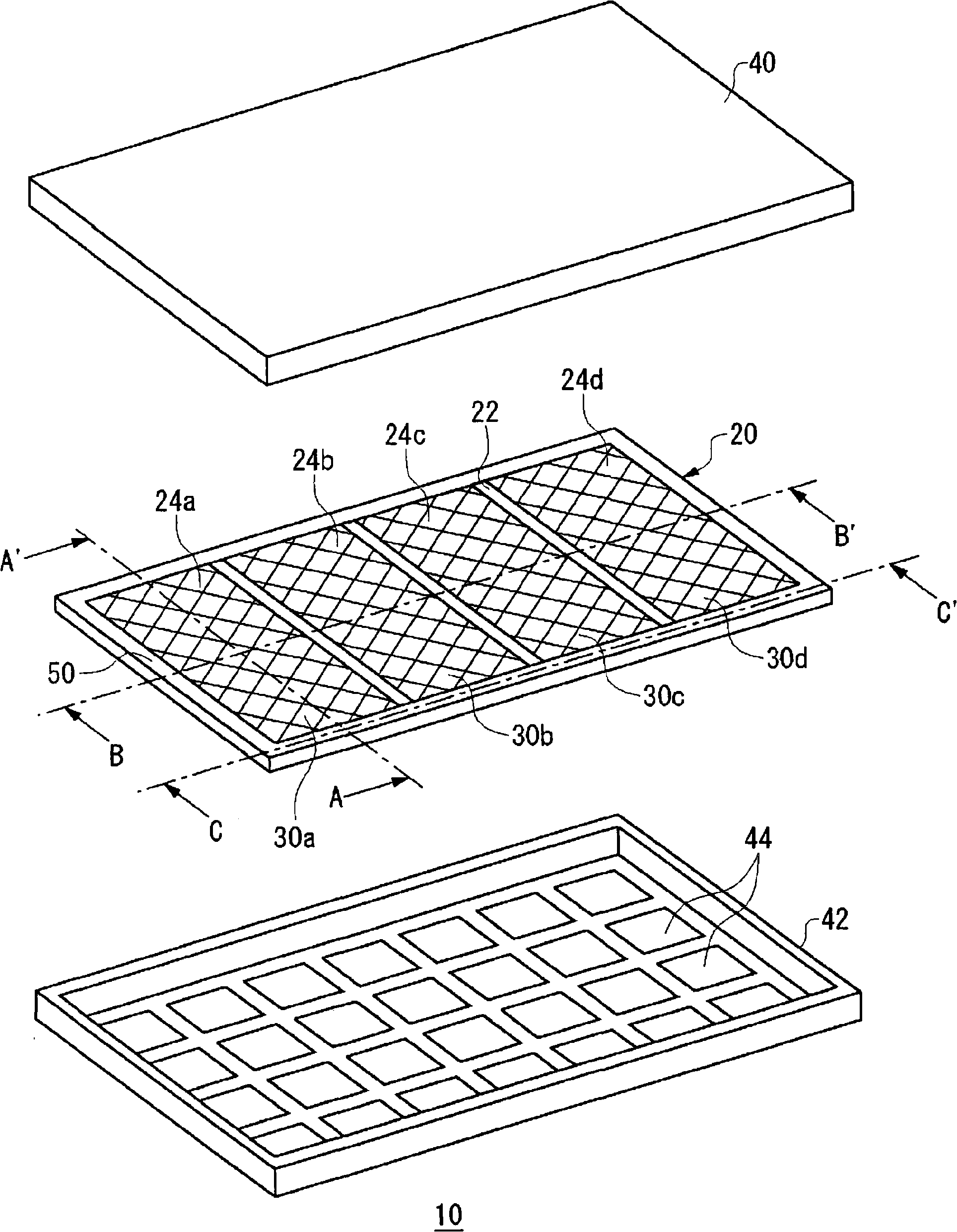
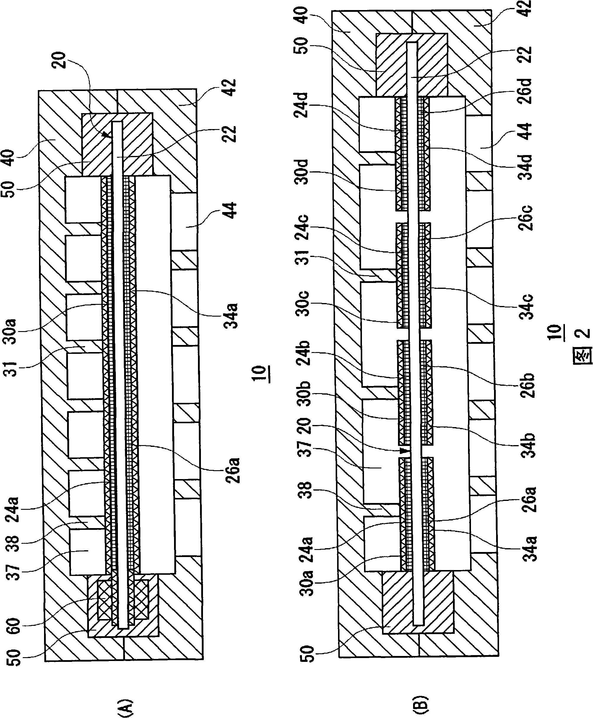
[0029] figure 1 It is an exploded perspective view showing the structure of the embodiment. Figure 2(A) and Figure 2(B) are respectively figure 1 A-A’ online, figure 1 A cross-sectional view on the line B-B' of . like figure 1 As shown in FIG. 2 , the fuel cell 10 includes a membrane electrode assembly (MEA, catalyst-coated proton exchange membrane (also referred to as CCM)) 20 , an anode case 40 and a cathode case 42 . In addition, a sealing member 50 to be described later is provided on the peripheral portion of the membrane electrode assembly 20 .

[0030] The membrane electrode assembly 20 includes an electrolyte membrane 22, anodes 24a-d, and cathodes 26a-d respectively facing the anodes 24a-d. Fuel is supplied to the anodes 24a-d. Air is supplied to the cathodes 26a-d. The fuel cell 10 generates electricity using an electrochemical reaction between fuel and oxyge...


PUM


Abstract

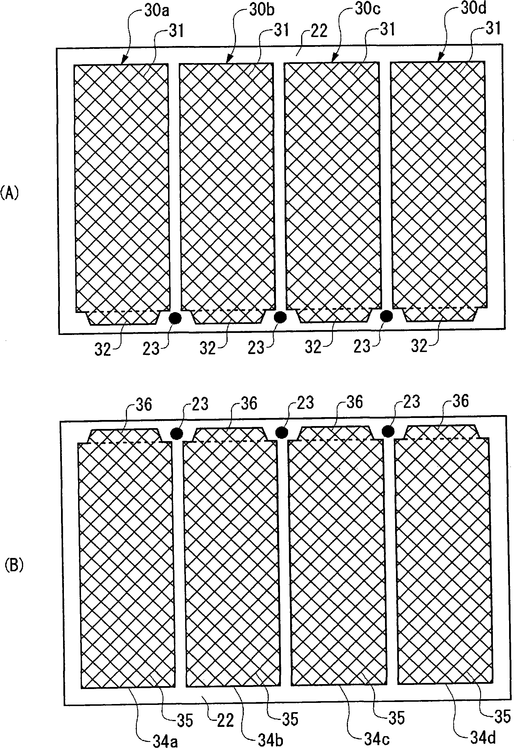
The present inventio provides a fuel cell and connection method of collecting body for the fuel cell. In a planar-array cell structure, an area required by interconnectors is reduced and a fuel cell is made further compact. A connection part which connects adjacent cells in series is provided within a sealing member provided in a peripheral edge part of an electrolyte membrane where multiple cells are formed in a planar arrangement. For each cell, an anode terminal of a current collector is disposed counter to a cathode terminal of the current collector via the electrolyte membrane. The connection part penetrates the electrolyte membrane and connects the anode terminal of one of the adjacent cells to the cathode terminal of the other of the adjacent cells.

Description

technical field [0001] The present invention relates to fuel cells. More specifically, the present invention relates to a fuel cell in which single cells are arranged planarly and a method for connecting current collectors. Background technique [0002] A fuel cell is a device that generates electricity from hydrogen and oxygen, and can achieve high power generation efficiency. As the main features of the fuel cell, since it is a direct power generation that does not go through the thermal energy and kinetic energy process like the existing power generation method, it can be cited that high power generation efficiency can be expected even in a small scale, and there is no discharge of nitrides, etc. And the noise and vibration are small, so the environmental protection is good. In this way, the fuel cell has the characteristics of being able to effectively utilize the chemical energy of the fuel and is excellent in environmental protection. Therefore, it is expected to be ...

Claims


Application Information

Patent Timeline
Patent Type & Authority Applications(China)
IPC IPC(8): H01M8/10H01M8/02H01M4/86H01M4/88
CPCH01M8/0247H01M8/0271H01M2008/1095Y10T29/49169Y02E60/50H01M8/2418
Inventor 井村真一郎安尾耕司
Owner SANYO ELECTRIC CO LTD
Learn More