Eureka AIR delivers breakthrough ideas for toughest innovation challenges, trusted by R&D personnel around the world.

Beam neutralization in low-energy high-current ribbon-beam implanters

An electron and ion beam technology, which can be used in circuits, discharge tubes, electrical components, etc., to solve the problems of difficult capture and difficulty in space charge neutralization.

Active Publication Date: 2008-09-03
VARIAN SEMICON EQUIP ASSOC INC
View PDF2 Cites 6 Cited by
  • Summary
  • Abstract
  • Description
  • Claims
  • Application Information

AI Technical Summary

Problems solved by technology

However, it should be emphasized that, especially during the generation of low energy ion beams, DC ribbon beam technology has its own special problems: these problems include the difficulty of space charge neutralization of beams with large transverse dimensions
Thus, trapping is difficult to achieve since even zero-energy electrons generated at a distance will tend to be accelerated through the beam and out the other side, and thus not trapped

Method used


Image

  • Beam neutralization in low-energy high-current ribbon-beam implanters
  • Beam neutralization in low-energy high-current ribbon-beam implanters
  • Beam neutralization in low-energy high-current ribbon-beam implanters

Examples


Embodiment Construction

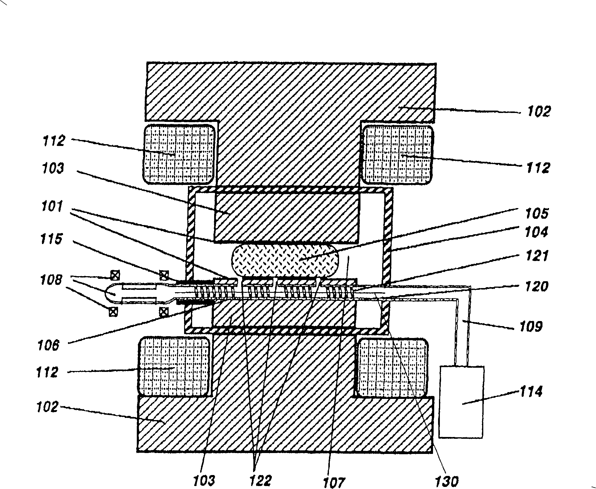
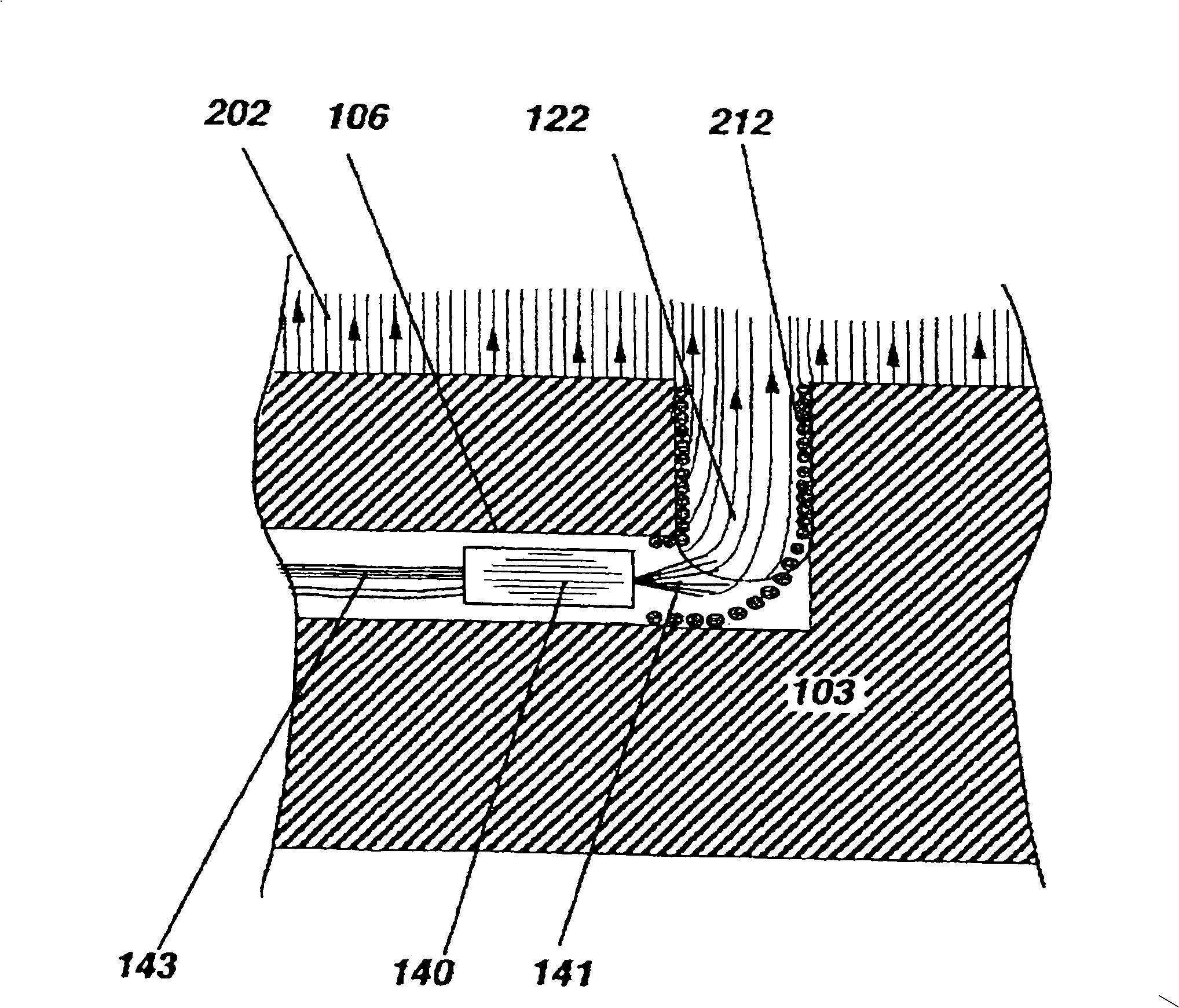
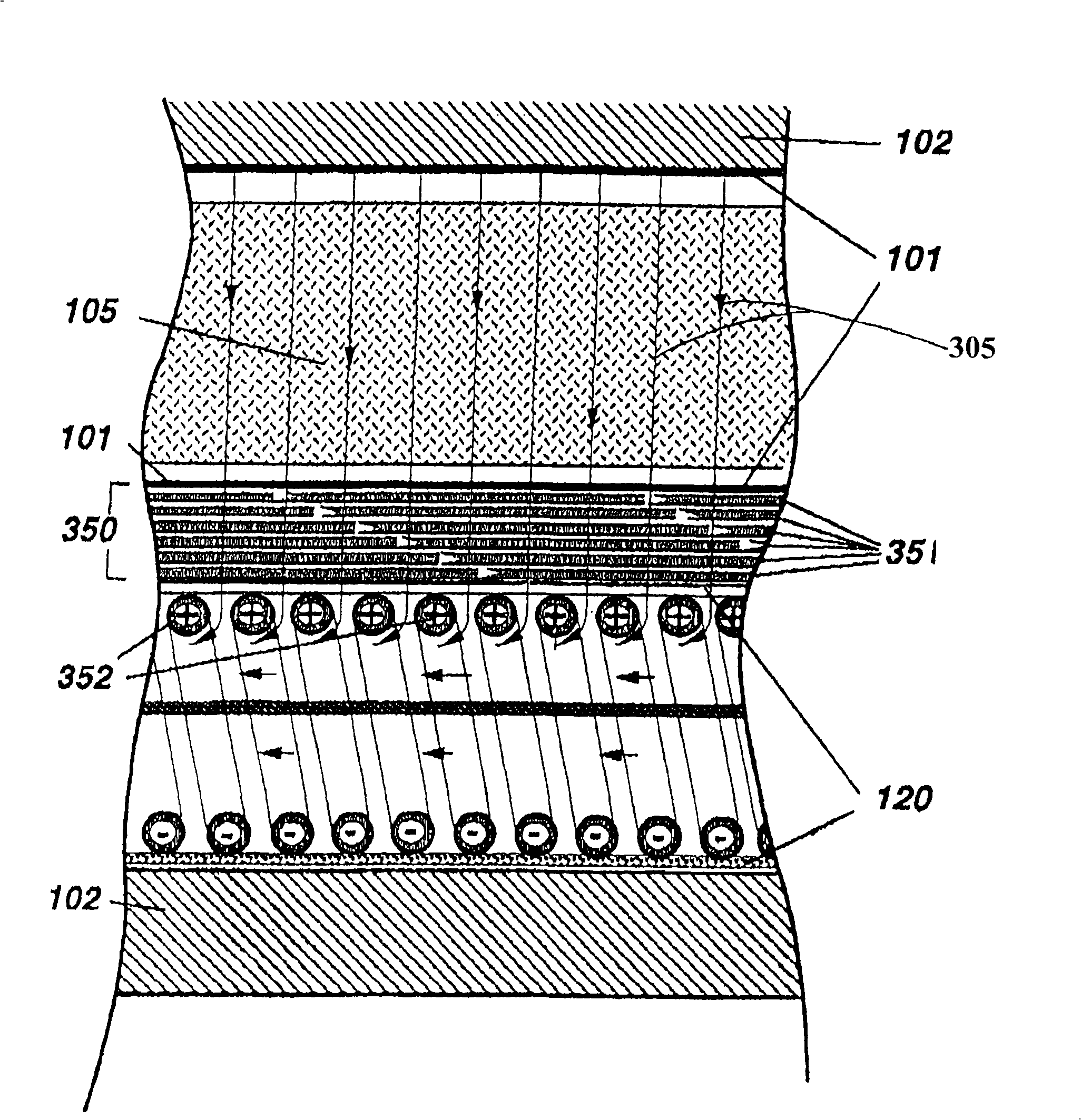
[0069] FIG. 1 illustrates a cross-section of a pole of a deflection magnet. In the preferred embodiment, the surface of the pole 103 is located within a vacuum chamber 104, although those skilled in the art will appreciate that the pole surface 101 may actually be part of an underlying magnetic return yoke 102. , not outside. A magnetic field is generated by the coil 112 . This allows the poles to be as close as needed to the ion beam trajectory 105 without wasting the distance of a wide vacuum-sealed enclosure that would require thick walls to withstand atmospheric pressure. A variable magnetic field can be actively introduced using surface windings described in Kenneth H. Purser and Norman L. Turner entitled "Broad Energy Range Ribbon Beam Collimation Using Variable Gradient Dipoles". Ion Beam Collimation Using a variable GradientDipole)" is described in detail in the companion patent application.

[0070] It can be seen that a hole 106 of suitable diameter is drilled thr...


PUM


Abstract

The fabrication of modern semiconducting integrated circuits often requires implantation steps that involve high currents of low-energy charged dopant atoms. When employing such beams, the addition of electrons or negative ions for neutralizing the effects of space charge is often crucial for achieving success. Without this supplement, ion beams can ''blow-up'' causing loss of intensity and disruption of beam focusing. In the present disclosure, methods are presented for introducing and constraining neutralizing low-energy electrons and negative ions within the boundaries of ribbon beams within regions of magnetic field deflection. Apparatus is described for maintaining neutralization based upon a reduction of electron losses, plasma bridge connections and secondary electron production. As part of plasma introduction to the deflection region a novel cryogenic pumping apparatus selectively removes neutral atoms from a plasma stream.

Description

[0001] This application claims priority to the following U.S. Provisional Patent Application: Serial No. 60 / 637,625, filed December 20, 2004, entitled "Improving Beam Neutralization in Low-Energy High Current Implanters" High-Current Implanter) "; Serial No. 60 / 638,848, the title submitted on December 23, 2004 is also "Improving Beam Neutralization in Low-Energy High-Current Implanter"; Serial No. 60 / 642,612, filed January 10, 2005, also entitled "Improving Beam Neutralization in Low-Energy High-Current Implanter"; and Serial No. 60 / 645,458, Also entitled "Improving Beam Neutralization in Low-Energy High-Current Implanter," filed January 19, 2005, the disclosures of these patent applications are incorporated by reference in their entirety at In this article. technical field [0002] The present invention relates to methods and apparatus for low energy high current ion implantation using ribbon beams. Specifically, the present invention utilizes electrons or negative ions to ...

Claims


Application Information

Patent Timeline
Patent Type & Authority Applications(China)
IPC IPC(8): A61N5/00G21G5/00
CPCH01J37/3171H01J2237/0042H01J2237/055H01J2237/057H01J37/026H01J37/08
Inventor 肯尼思·H·珀泽诺曼·L·特纳
Owner VARIAN SEMICON EQUIP ASSOC INC
Why Eureka
Eureka Blog
Learn More