Wet-type dust-removal fan

A wet dust removal and fan technology, which is applied in the directions of dispersed particle separation, chemical instruments and methods, combined devices, etc., can solve the problems of low air volume handling capacity and dust removal efficiency, easy to burn out fan motor maintenance work, and large resistance of dust removal system, etc. No need for frequent maintenance, significant energy-saving effect, and the effect of ensuring operational safety and work efficiency

Active Publication Date: 2008-09-10
郭峰
View PDF1 Cites 24 Cited by
  • Summary
  • Abstract
  • Description
  • Claims
  • Application Information

AI Technical Summary

Problems solved by technology

[0004] The purpose of the present invention is to provide a wet dust removal fan, which can achieve the purpose of effectively removing the dust in the dusty air without taking the form of filtration, and it can solve the problem of relatively large resistance of the dust removal system, air volume handling capacity and dust removal efficiency in the prior art. Low energy consumption, high energy consumption, easy to burn the fan motor and heavy maintenance work

Method used


Image

  • Wet-type dust-removal fan

Examples


Embodiment 1

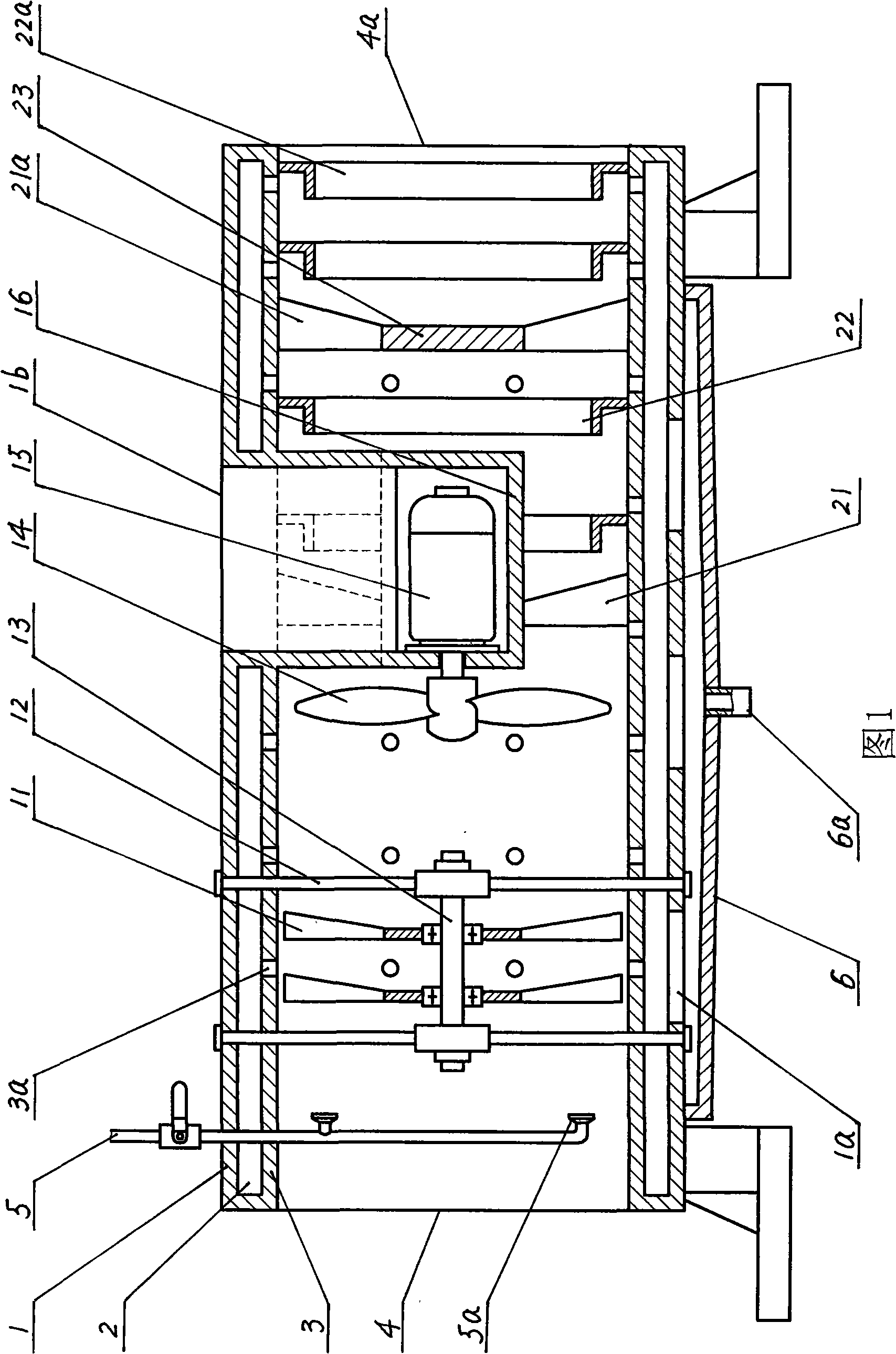
[0016] The front position in the air duct of the present invention is installed with water spray nozzle 5a, and the middle position is installed with the motor 15 of fan impeller 14; Open port 1b is offered on the air duct, and the protective shell 16 that is provided with heat dissipation port is arranged in the air duct, And it is connected with the blower, the port 1b communicates with the cooling port of the protective case 16 correspondingly, and the motor 15 is installed in the protective case 16 . The air cylinder is composed of an outer cylinder wall 1 and an inner cylinder wall 3 with several through holes 3a. There is a sandwich cavity 2 between the outer cylinder wall 1 and the inner cylinder wall 3; the bottom of the outer cylinder wall 1 is provided with a water outlet. 1a, the water storage box 6 is connected to the lower part of the outer cylinder wall 1, and corresponds to the water outlet 1a, and the bottom of the water storage box 6 is provided with a drainage...

Embodiment 2

[0019] On the basis of Embodiment 1, a plurality of water collection rings are respectively arranged at the rear positions of the two separated impellers 11 in the air cylinder, and there are intervals between them, and the plurality of water collection rings are respectively connected to the inner wall of the inner cylinder wall 3. It can make the dusty water flow on the inner wall of the inner cylinder wall 3 pass through the collection of the water collection ring, and then flow into the water storage box 6 regularly and be discharged. The water collecting ring can reduce the moisture content in the air, so as to avoid excessive humidity of the air discharged from the air outlet 4a.

Embodiment 3

[0021]On the basis of Embodiment 1, in the interval between the protective shell 16 and the inner cylinder wall 3, a first deflector composed of several first-stage deflector vanes 21 arranged in a circle is arranged, each of which is The outer ends of the first-stage guide vanes 21 are respectively connected to the inner cylinder wall 3, and the inner ends are respectively connected to the protective shell 16; There are intervals between them. The swirling centrifugal force generated by the first deflector can throw the dust-laden liquid droplets onto the inner cylinder wall 3 provided with several through holes 3a again, and the dust-laden liquid droplets enter the interlayer cavity 2 through the through holes 3a and fall. After entering the water storage box 6, it is discharged through the drain port 6a; in addition, the dusty water flow on the inner wall surface of the inner cylinder wall 3 is collected by two first-stage water collection rings 22 arranged in sections and ...


PUM

PropertyMeasurementUnit
dust removal efficiencyaaaaaaaaaa

Abstract

The invention discloses a wet dust removal fan, which comprises a wind-cone. The wind-cone consists of the wall of an outer cone and the wall of an inner cone which is provided with a plurality of through holes. A sandwich cavity is arranged between the wall of the outer cone and the wall of the inner cone; a flow port is opened at the bottom of the wall of the outer cone; a seeper box is connected with the lower part of the wall of the outer cone and is correspondent to the flow port; an outlet is arranged at the bottom of the seeper box; the inner wall of the inner cone is provided with a support which is equipped with an axle; the support is connected with the wind-cone and is arranged between a water injection nozzle and a fan wheel, and the axle is provided with at least a separating blade. The wet dust removal fan has the advantages of high purification efficiency in the practical application, low operational cost, notable energy saving effect and no frequent maintenance, which completely solves the problems that large resistance of the dust removing system exists owning to a filter screen, the handling ability of blast volume is bad, the increasing of the loading of a fan motor is directly affected by the dust capacity adsorbed of and the fan motor is burnt down easily owing to the phenomenon of blocking, thus ensuring the operation safety and work efficiency of the fan motor.

Description

technical field [0001] The invention relates to the technical field of dedusting equipment, in particular to a wet dedusting blower used for removing dust in the ambient air of a working surface in a mine. Background technique [0002] At present, in places with serious dust pollution such as underground mines and tunnel construction, most of them use filter-type dust removal devices to filter the dust in their working environment, so as to purify the ambient air on the working surface and effectively protect the health of workers. the goal of. This filter-type dust removal device adopts the repeated circulation method of the dust-laden air in the working surface environment through the filter, that is: the dust-laden air is condensed under the action of water mist to form a dust-water mixture, which is filtered by the filter and then dehydrated. discharge. The existing problems are: 1. Because the filter is composed of multi-layer filter screens, its mesh is extremely sma...

Claims


Application Information

Patent Timeline
Patent Type & Authority Applications(China)
IPC IPC(8): B01D50/00
Inventor 郭峰郭金郭光
Owner 郭峰
Why Eureka
Try Eureka