
Micro- solid mode gyroscope

A micro-solid, modal technology, applied in the direction of gyroscopic effect for speed measurement, gyroscope/steering sensing equipment, measurement device, etc., can solve the problem of limited microfabrication performance of piezoelectric ceramics, limited material selectivity, and low feasibility. problems, to achieve the effect of increasing micromachinability, strong anti-vibration ability, and improving work performance

Inactive Publication Date: 2008-09-10
SHANGHAI JIAO TONG UNIV
View PDF0 Cites 14 Cited by
  • Summary
  • Abstract
  • Description
  • Claims
  • Application Information

AI Technical Summary

Problems solved by technology

The elasticity and micromachinability of piezoelectric ceramics are limited, and the material and electrical properties of piezoelectric ceramics are sensitive to temperature, which limits the improvement of the manufacturing accuracy of this microgyroscope. Its material selectivity is limited and microfabrication is batched. Manufacturing feasibility is not high

Method used


Image

  • Micro- solid mode gyroscope
  • Micro- solid mode gyroscope

Examples


Embodiment Construction

[0017] The embodiments of the present invention are described in detail below in conjunction with the accompanying drawings: the present embodiment is implemented on the premise of the technical solution of the present invention, and detailed implementation methods and processes are provided, but the protection scope of the present invention is not limited to the following implementations example.

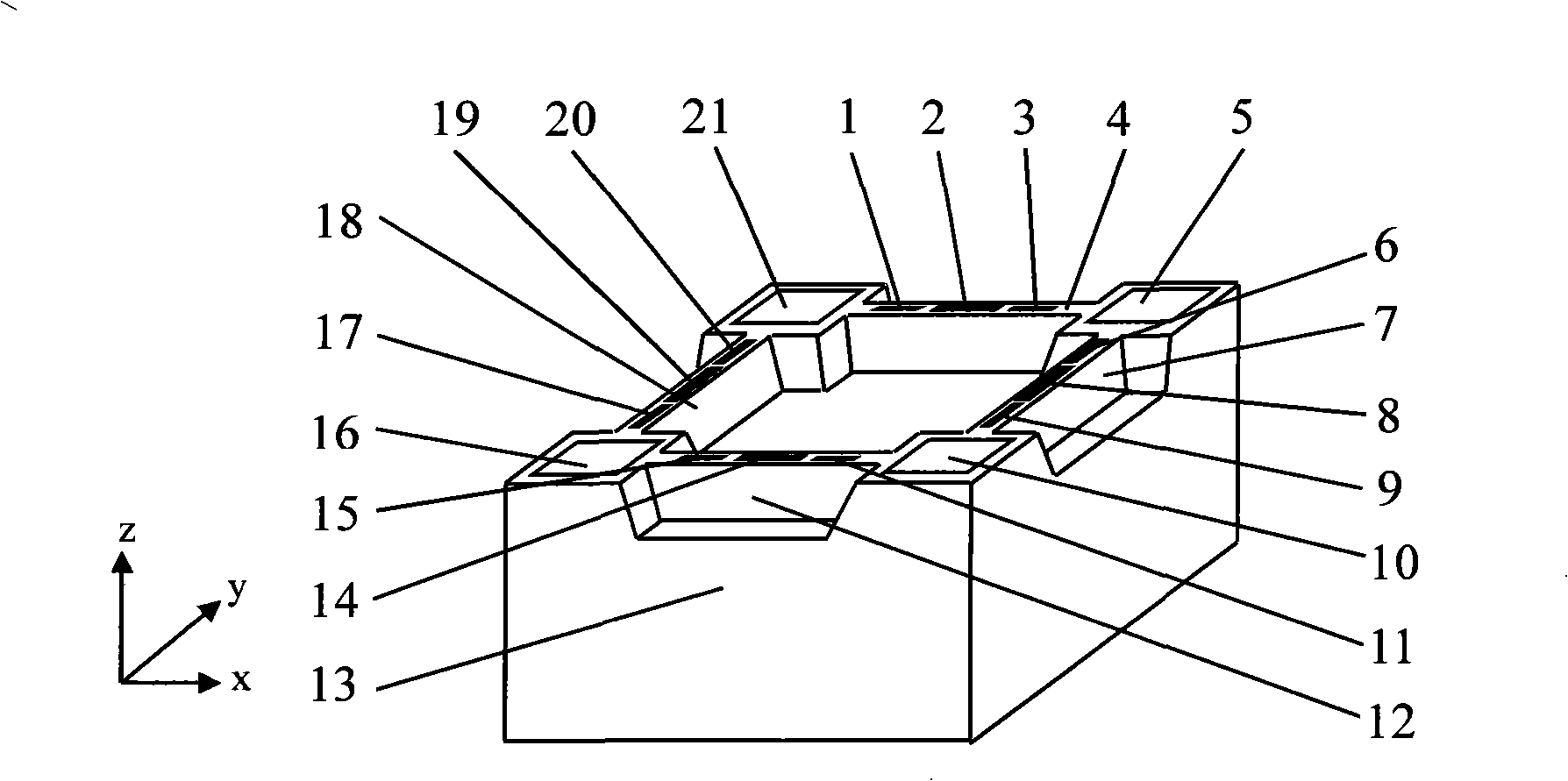
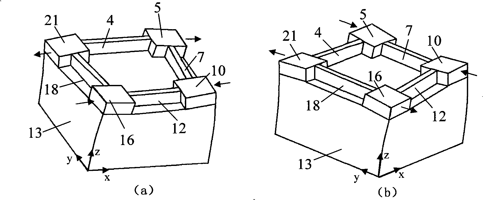
[0018] Such as figure 1 As shown, this embodiment includes: four pairs of piezoelectric control electrodes 1, 3, 6, 9, 11, 15, 17, 19, two piezoelectric sensing electrodes 2, 14, and two piezoelectric driving electrodes 8, 19 , four lumped masses 5, 10, 16, 21, four linear vibration enhancement structures 4, 7, 12, 18, and an elastic matrix 13.

[0019] The elastic base 13 is made of a material with good elasticity, such as metal, glass or polymer material. The linear vibration enhancing structures 4 , 7 , 12 , 18 are formed on the elastic base 13 by wet etching, and the linear v...


PUM


Abstract

The invention provides a micro-solid modal gyro in the micro electromechanical system technical field, comprising a piezoelectric control electrode, a piezoelectric sensing electrode, a piezoelectric driving electrode, a concentrated mass block, a linear vibration reinforced structure and an elastic base. The elastic base is provided with linear vibration reinforced structure; the linear vibration reinforced structure and the elastic base are fixedly connected with each other; the upper surface of the elastic base is provided with a trough which is internally provided with the concentrated mass block; the concentrated mass block is fixedly connected with the elastic base; the upper surface of the linear vibration reinforced structure is provided with the piezoelectric sensing electrode, the piezoelectric driving electrode and the piezoelectric control electrode. The micro-solid modal gyro works by the special vibration mode of the elastic base, increases the selectable freedom of the fabrication material of the micro gyro, leads the elastic base to be made of material with larger elasticity, and increases the micro-processability of the base material, thus being beneficial to improve the structure and shape of the micro gyro and improving the working performance of the gyro.

Description

technical field [0001] The invention relates to a device in the technical field of micro-electromechanical systems, in particular to a micro-solid mode gyroscope. Background technique [0002] Over the past century, gyro technology has undergone a series of revolutionary developments. At the beginning of the 20th century, Elmer Sperry invented the gyro compass and applied it in navigation. In the 1950s, the use of frame gyro and accelerometer systems to sense the six degrees of freedom of the aircraft has been realized. These early gyro systems were used for azimuth reference only, so no high accuracy requirements were placed on them. Due to the high complexity and high cost of the frame gyro system, the strapdown inertial reference system began to be developed in the 1970s. In order to obtain sufficiently high performance, the strapdown system requires high precision, and its gyro precision drift should be lower than 0.01deg / h. In order to meet such precision requiremen...

Claims


Application Information

Patent Timeline
Patent Type & Authority Applications(China)
IPC IPC(8): G01C19/56G01P9/04G01C19/5656
Inventor 吴校生陈文元
Owner SHANGHAI JIAO TONG UNIV
Learn More