A loop concave output mirror laser resonance cavity

A laser resonator and output mirror technology, applied in the field of laser resonators, can solve the problems of small gain devices not suitable, high adjustment precision requirements, large loss, etc., and achieve low beam center power density, low manufacturing cost, and high performance reliable effect

Inactive Publication Date: 2008-09-10
HUAZHONG UNIV OF SCI & TECH
View PDF0 Cites 10 Cited by
  • Summary
  • Abstract
  • Description
  • Claims
  • Application Information

AI Technical Summary

Problems solved by technology

The main disadvantages of the parallel plane cavity are: the adjustment accuracy is extremely high and it is easy to misalign. Compared with the stable cavity, the loss is also large, and it is not suitable for small gain devices.

Method used


Image

  • A loop concave output mirror laser resonance cavity
  • A loop concave output mirror laser resonance cavity
  • A loop concave output mirror laser resonance cavity

Examples


Embodiment 1

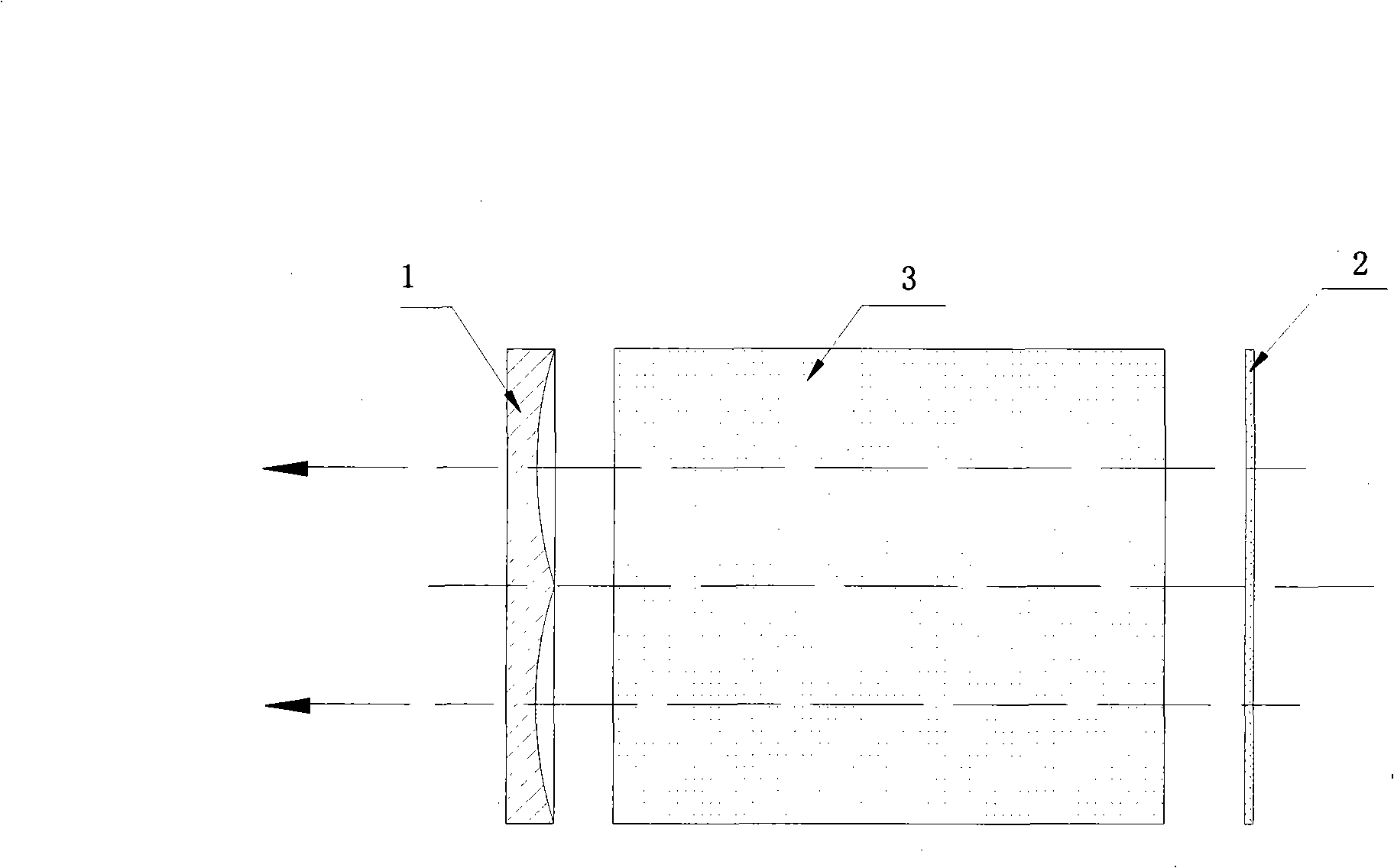
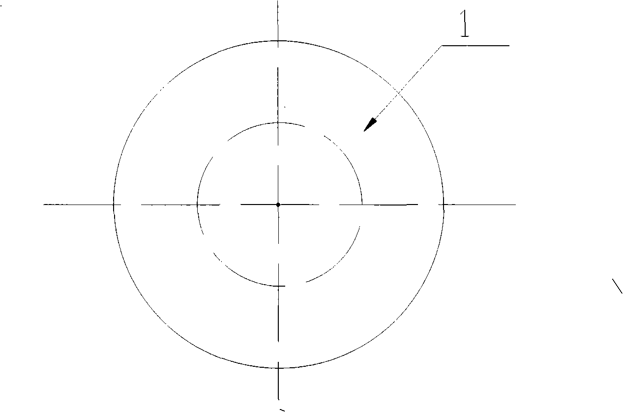
[0041] Depend on Figure 1 ~ Figure 2 As shown, a laser resonator with an annular concave output mirror includes a reflector 2, a laser working medium 3 and an output mirror 1. The output mirror 1 is an annular concave output mirror, and its working surface is composed of an annular arc-shaped concave surface.

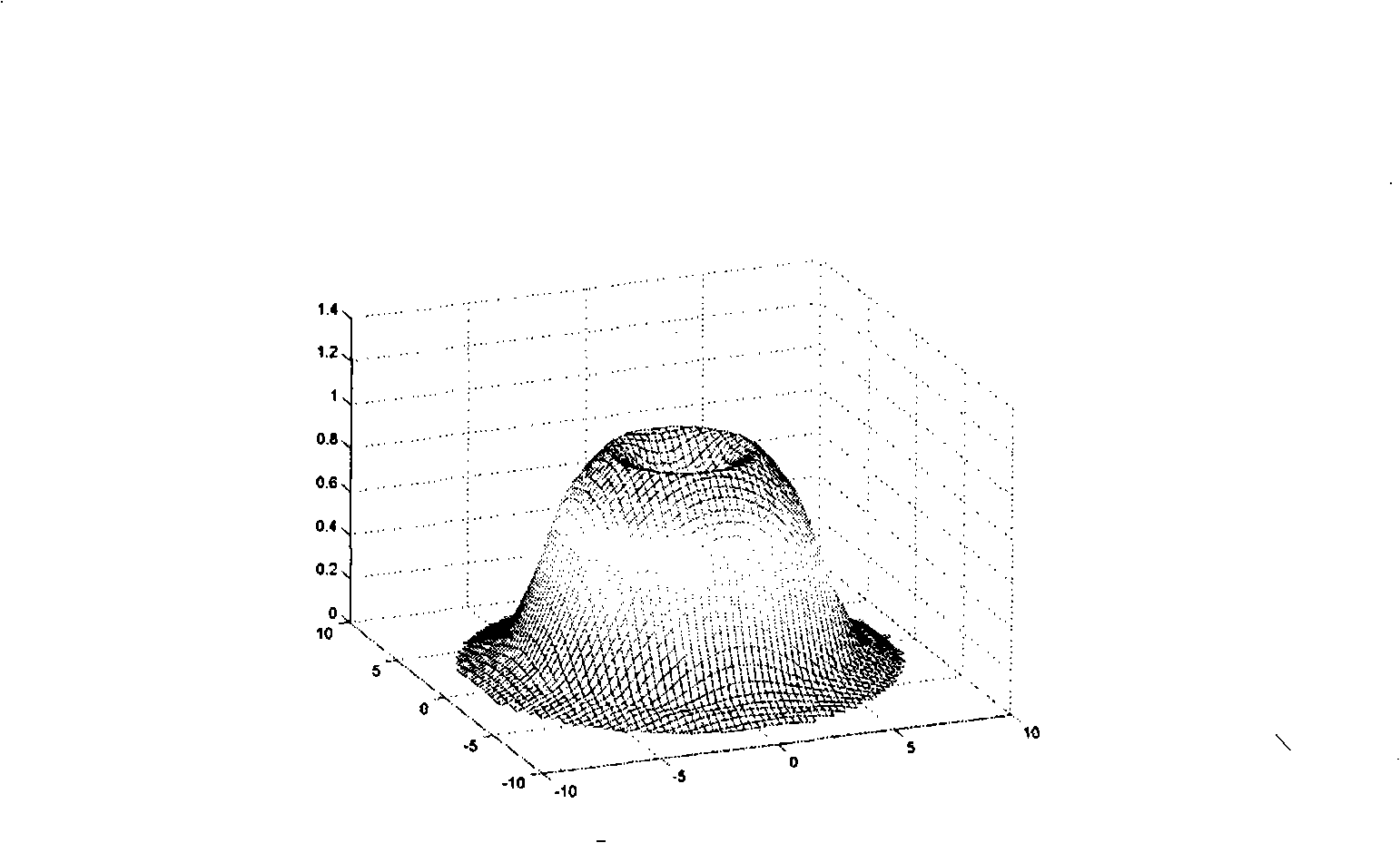
[0042] Analysis of the laser resonator in Example 1 shows that the output beam of the laser resonator of the annular concave output mirror is annular, and the power peak position is not at the center of the mirror, but on a circle with the center of the mirror as the center, which can reduce the output The temperature of the mirror, reflector and the center of the outer optical path lens reduces thermal deformation and improves beam stability. image 3 It is a schematic diagram of the output beam of Embodiment 1 of the present invention. Compared with the stable cavity, the laser resonator adopts the annular concave output mirror to ensure the quality of the output la...

Embodiment 2

[0044] Depend on Figure 4 ~ Figure 5 As shown, the output mirror 1 is an annular concave output mirror, and its working surface is composed of an annular arc-shaped concave surface and a central circular working surface. The above-mentioned central circular working surface can be a plane or a spherical surface.

[0045] Analysis of the laser resonator in Example 2 shows that the output beam of the laser resonator of the annular concave output mirror is annular, and the power peak position is not at the center of the mirror, but on a circle with the center of the mirror as the center, which can reduce the output The temperature of the mirror, reflector and the center of the outer optical path lens reduces thermal deformation and improves beam stability. Compared with the stable cavity, the laser resonator with annular concave output mirror can greatly increase the mode volume and greatly increase the laser output power under the condition that the quality of the output laser ...

Embodiment 3

[0047] Depend on Figure 6 ~ Figure 7 As shown, the output mirror 1 is an annular concave output mirror, its working surface includes an annular arc-shaped concave surface, the center of the mirror surface is a non-working surface or hollow, and the laser working medium 3 is an annular cylindrical working medium.

[0048]Analysis of the laser resonator of embodiment 3 shows that the laser resonator output beam of the annular concave output mirror is annular, and the power peak position is not at the center of the mirror, but on a circle with the center of the mirror as the center, which can reduce the The temperature of the output mirror, reflector and the center of the outer optical path lens reduces thermal deformation and improves beam stability. Compared with the stable cavity, the laser resonator using the annular concave output mirror can greatly increase the laser output power under the condition that the quality of the output laser beam is guaranteed and the divergence...


PUM


Abstract

The invention discloses a laser resonant cavity with an annular and a concave output mirror, which comprises a reflecting mirror, a laser medium and an output mirror; the output mirror is an annular concave mirror of which the working surface comprises one or a plurality of homocentric, annular and circular arc shaped concave cambers; the central part of the working surface of the output mirror can also be a circular working surface or the central part of the out mirror can be non-working surface or hollowness; an annular and concave reflecting mirror can also be adopted by the laser resonant cavity of the invention. The laser resonant cavity provided by the invention has the advantages of simple processing, convenient adjustment, steady operation, large available mode volume, very small divergence angle and good beam quality, thus being able to be applicable to gas lasesr or solid lasers with medium and high power, in particular to large volume gain medium and cylindrical and toroidal gain medium.

Description

technical field [0001] The invention relates to a laser resonant cavity, in particular to a laser resonant cavity with an annular concave output mirror. Background technique [0002] In many occasions of laser application, such as laser drilling, welding, cutting and laser medical treatment, etc., it is hoped that the laser can work in the fundamental mode state with the smallest divergence angle and the best beam quality. Traditional mode selection techniques (such as using an aperture stop) can improve the quality of the laser output beam, but the use of an aperture stop limits the mode volume to a large extent and increases the mode loss. [0003] The key to the design of high-power laser devices is how to achieve high-power single-mode operation while obtaining the largest possible mode volume and good transverse mode discrimination ability, so as to extract energy efficiently from the active material while maintaining high beam quality. [0004] There are three types ...

Claims


Application Information

Patent Timeline
Patent Type & Authority Applications(China)
IPC IPC(8): H01S3/08
Inventor 秦应雄唐霞辉程祖海肖龙胜李根肖瑜
Owner HUAZHONG UNIV OF SCI & TECH
Why Eureka
Try Eureka