Welding technology for large and middle-scale synchronous generator stator bar connection wire

A technology for synchronous generators and stator bars, which is applied in the manufacture of motor generators, connections, circuits, etc., can solve the problems of waste of copper and insulating materials, insufficient bending strength, and inability to clamp wire bars, etc. Silver solder, expanded design range, improved soldering quality

Inactive Publication Date: 2008-09-10
TIANJIN TIRNFR HEAVY HYDROELECTRIC FRCILITY CO LTD
View PDF0 Cites 4 Cited by
  • Summary
  • Abstract
  • Description
  • Claims
  • Application Information

AI Technical Summary

Problems solved by technology

In order to ensure the welding distance, the stator bar always enlarges the radius of the connecting wire. At present, the distance between the joints of domestic and foreign units is generally controlled above 38mm to ensure the welding process requirements of the joints, resulting in waste of copper and insulating materials. In order to save expensive wires Rod material and to improve the ventilation conditions at the end of the wire rod, the designer always hopes to make the joint spacing close to the slot spacing
However, this makes the welding space between the wire rods relatively reduced. The existing welding clamping device has a large splint thickness, and the waterways are arranged in parallel. The splint is made of red copper material, and the bending strength after heating is not high enough. In addition, the design capacity of the current generator set is continuously improved, and the depth of the stator slot is increased. The splint is required to be longer and thinner, which makes the existing welding clamp The problem that the splint of the device cannot clamp the wire rod due to insufficient bending strength is more prominent. Therefore, the existing large and medium-sized synchronous generator stator wire rod connecting wire welding process can no longer meet the current large and medium-sized synchronous generator stator wire rod connection. New requirements for wire bonding

Method used


Image

  • Welding technology for large and middle-scale synchronous generator stator bar connection wire
  • Welding technology for large and middle-scale synchronous generator stator bar connection wire
  • Welding technology for large and middle-scale synchronous generator stator bar connection wire

Examples


Embodiment Construction

[0020] In order to further understand the invention content, characteristics and effects of the present invention, the following examples are given, and detailed descriptions are as follows in conjunction with the accompanying drawings:

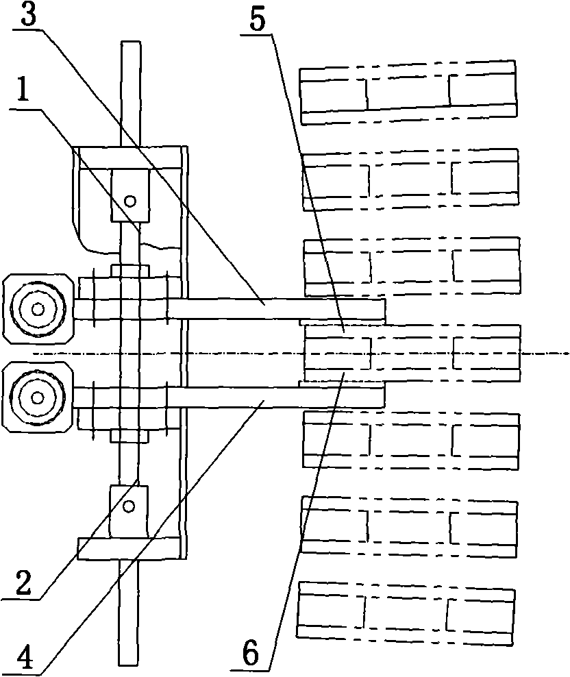
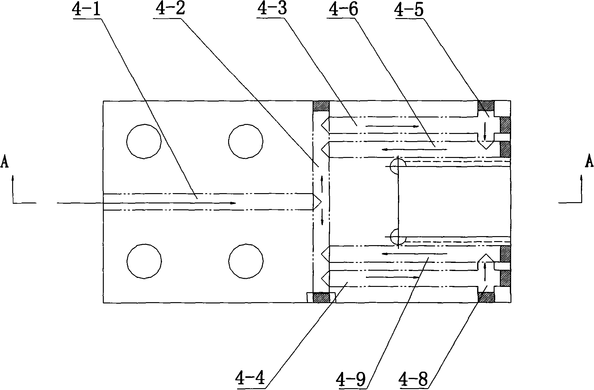
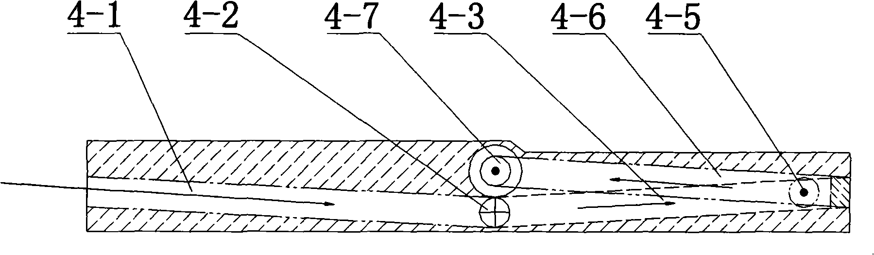
[0021] see figure 1 , Figure 4 , Figure 5 , in the figure, the arrow indicates the water flow direction, ● indicates the water outlet, × indicates the water inlet, a indicates the silver soldering part, figure 1 It is a structural schematic diagram of implementing the present invention, a large and medium-sized synchronous generator stator bar connection wire welding process, including the following steps:

[0022] 1. Welding rod 7 upper end connector

[0023] (1) Extend the splints 3 and 4 of the clamping device to the joints of the lower layer wire rod 7-2 and the connection plate 5, pressurize the splints 3 and 4, pass water, and energize, and weld the connection plate 5 and the lower layer wire rod 7 -2;

[0024] (2) The splints 3 ...


PUM


Abstract

The invention relates to a connecting coil welding technique for a stator bar of a large or middle synchronous generator, the technique is characterized in that: the technique comprises the following steps: 1. upper joints of coil bars are welded: (1) the splint of a clamping device is stretched into a part where a lower layer coil is connected with a connecting plate, the splint is stressed, water and power are put through and the connecting plate and the lower layer coil are welded; (2) the splint of the clamping device is backed to the part where an upper layer coil is connected with the connecting plate, the splint is stressed, water and power are put through and the connecting plate and the upper layer coil are welded; (3) connecting coils of all coil slots and interelectrode connecting coils are welded according to the steps (1) and (2) in sequence; 2. lower joints of coil bars are welded according to the step (1). The technique provided by the invention can extend design range of motor windings, reduce the amount of stator winding copper materials and insulation materials, save lots of silver solder, improve welding quality and reduce overall cost of units.

Description

technical field [0001] The invention relates to a manufacturing process of power generation mechanical equipment, in particular to a welding process for connecting wires of stator bars of large and medium-sized synchronous generators. Background technique [0002] At present, the connection of stator windings of large and medium-sized synchronous generators mostly adopts the structure of connecting plate and wire bar silver welding. The distance is basically fixed. In order to ensure the welding distance, the stator bar always enlarges the radius of the connecting wire. At present, the distance between the joints of domestic and foreign units is generally controlled above 38mm to ensure the welding process requirements of the joints, resulting in waste of copper and insulating materials. In order to save expensive wires In order to improve the rod material and improve the ventilation conditions at the end of the wire rod, the designer always hopes to make the joint spacing ...

Claims


Application Information

Patent Timeline
Patent Type & Authority Applications(China)
IPC IPC(8): H02K15/00H01R43/02
Inventor 赵作勤张俊新
Owner TIANJIN TIRNFR HEAVY HYDROELECTRIC FRCILITY CO LTD
Why Eureka
Try Eureka