Composite absorption heat pump of second type

An absorption heat pump and heat pump technology, applied in heat pumps, sorption machines, energy-saving heating/cooling, etc., can solve the problems of heat pumps that cannot obtain satisfactory energy-saving effects, reduced economic benefits, and low performance index.

Active Publication Date: 2008-09-17
李华玉
View PDF0 Cites 11 Cited by
  • Summary
  • Abstract
  • Description
  • Claims
  • Application Information

AI Technical Summary

Problems solved by technology

The process and structure of the second type of single-stage absorption heat pump are generally simplified, but its heating temperature and performance index, that is, the utilization rate of waste heat, cannot be unified-the higher the heat pump stage, the higher the heating temperature. The higher the performance index is, the lower the performance index is; on the contrary, the lower the heat pump stage is, the higher the performance index is, but the lower the heating temperature is.
When the heated fluid needs to be heated from a lower temperature to a higher temperature, limited by the temperature and quantity of waste heat resources and the conditions of the cooling medium, the use of a single-stage heat pump often cannot obtain satisfactory energy-saving effects; different stages The combined heating system composed of high-quality heat pumps can meet the heat demand of users in a wide temperature range, and can realize the application of waste heat to a higher degree at the same time, but this greatly increases the cost of the entire energy-saving heating system and complicates the operation of the system. The economic benefits are greatly reduced, and even the economic requirements cannot be met

Method used


Image

  • Composite absorption heat pump of second type
  • Composite absorption heat pump of second type

Examples


Embodiment Construction

[0014] The present invention will be described in detail below in conjunction with the accompanying drawings and examples.

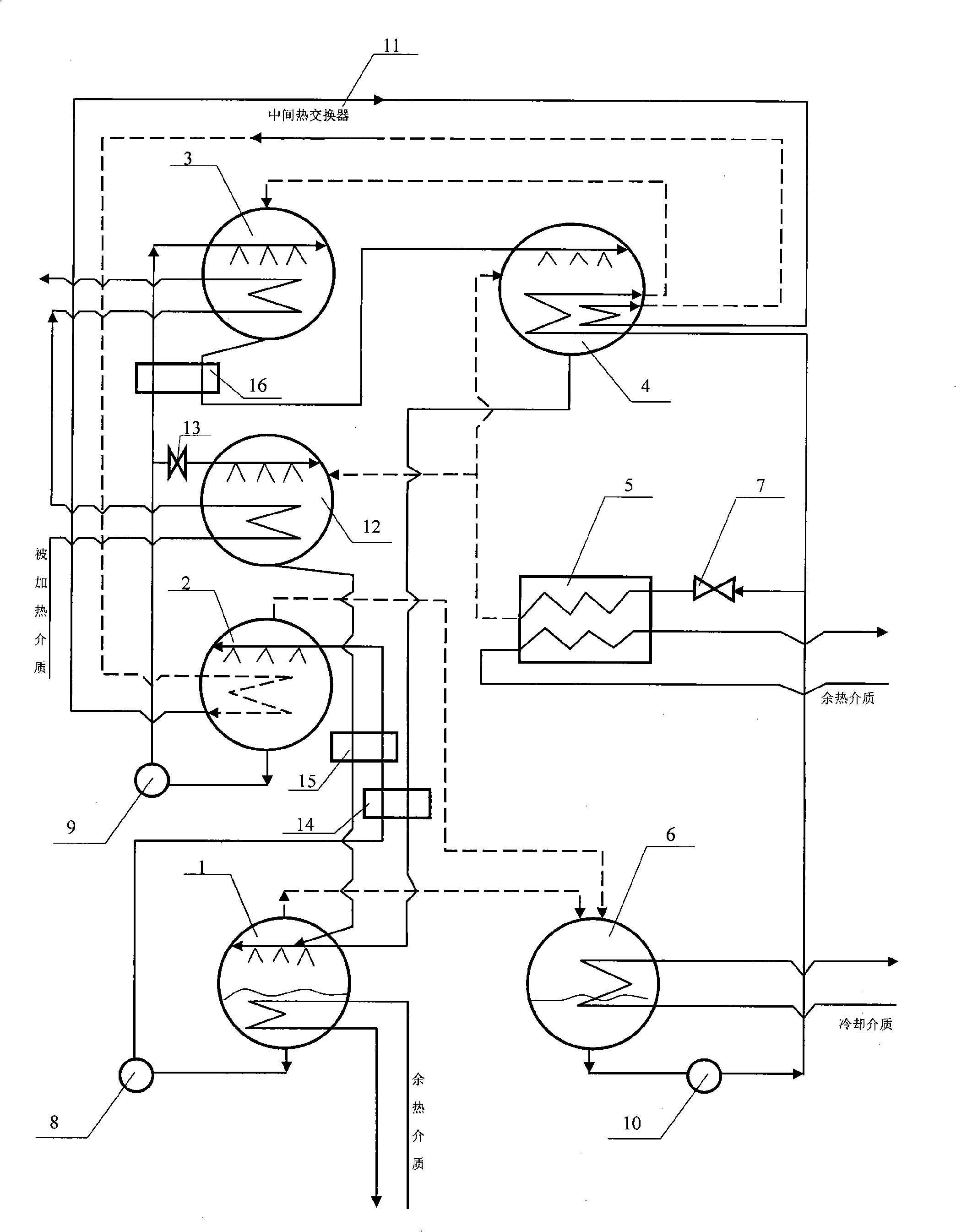
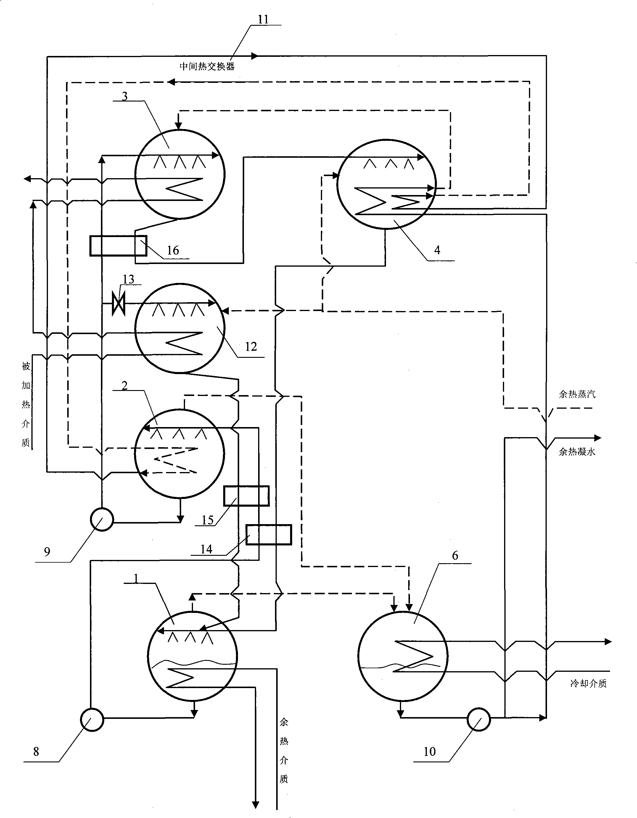
[0015] Take the compound second-type absorption heat pump system provided by the present invention for two-stage heating of the heated medium as an example, such as figure 1 Shown, the purpose of the present invention is achieved like this:

[0016] Structurally, it consists of primary generator 1, secondary generator 2, high temperature absorber 3, absorption-evaporator 4, evaporator 5, condenser 6, throttle valve 7, first solution pump 8, second solution In the heat pump structure composed of pump 9, refrigerant liquid pump 10, intermediate heat exchanger 11 and several solution heat exchangers 14, 16, a low-temperature absorber 12 and a solution regulating valve 13 are added so that the low-temperature absorber 12 passes through the second solution pump 9. The solution regulating valve 13 has a solution pipeline connected to the secondary generator 2...


PUM


Abstract

The invention provides a composite second absorption heat pump, belonging to the heat pump technology field, mainly comprising a plurality of generators, a high-temperature absorber, a low-temperature absorber, an absorption-evaporator, an evaporator, a condenser, a reducer, a regulating valve, a solution pump and a cold agent pump. The steam of cold agent generated by the generator goes into the condenser, and then cold agent pump provides the cold agent to the evaporator and the absorption-evaporator, and then the cold agent which is throttled and flows into the evaporator absorbs heat and is gasified and then flows into the low-temperature absorber, the absorption-evaporator, and then the cold agent in the absorption-evaporator absorbs heat and is gasified and flows into the high-temperature absorber; thin solution absorbs heat and releases steam with gradually increased consistency, and the steam of the cold agent which flows into the low-temperature absorber and the high-temperature absorber releases heat thereby supply heat for outside. The solution respectively flows through the high temperature absorber, the absorption-evaporator for gradually absorbing the cold agent steam, and flows through the low-temperature absorber for absorbing the cold agent steam, so that the consistency of the steam is reduced and the solution flows into a first-level generator; an intermediate heat-exchanger conducts heat between the absorption-evaporator for heating the solution.

Description

Technical field: [0001] The invention belongs to the technical field of low-temperature waste heat utilization heat pumps. Background technique: [0002] On the premise of meeting the heat demand of users, the heat pump should have the simplest possible process, structure and high performance index, so that the heat pump, an energy-saving device, has the advantages of low cost, simple and reliable operation, high performance index and good economic benefits, etc. Comprehensive advantages. [0003] When the waste heat temperature is high and the waste heat is relatively abundant, the use of the second type of absorption heat pump technology is the most effective way to achieve high efficiency and energy saving. The process and structure of the second type of single-stage absorption heat pump are generally simplified, but its heating temperature and performance index, that is, the utilization rate of waste heat, cannot be unified-the higher the heat pump stage, the higher the...

Claims


Application Information

Patent Timeline
Patent Type & Authority Applications(China)
IPC IPC(8): F25B15/00F25B30/04
CPCY02B30/62Y02A30/27
Inventor 李华玉
Owner 李华玉
Why Eureka
Try Eureka