Device and method for in-system programming for programmable logic device

A programming logic and system programming technology, applied in memory systems, measuring devices, instruments, etc., can solve problems such as large storage units, poor fault tolerance, and inability to explicitly distinguish, and achieve the effect of solving large consumption of storage resources

Inactive Publication Date: 2008-09-17
ZTE CORP
View PDF0 Cites 11 Cited by
  • Summary
  • Abstract
  • Description
  • Claims
  • Application Information

AI Technical Summary

Problems solved by technology

[0024] The present invention is made in consideration of the problems in the related art of consuming large storage units, poor fault tolerance, and the inability to clearly distinguish the various stages of the entire system programming process

Method used


Image

  • Device and method for in-system programming for programmable logic device
  • Device and method for in-system programming for programmable logic device
  • Device and method for in-system programming for programmable logic device

Examples


example 1

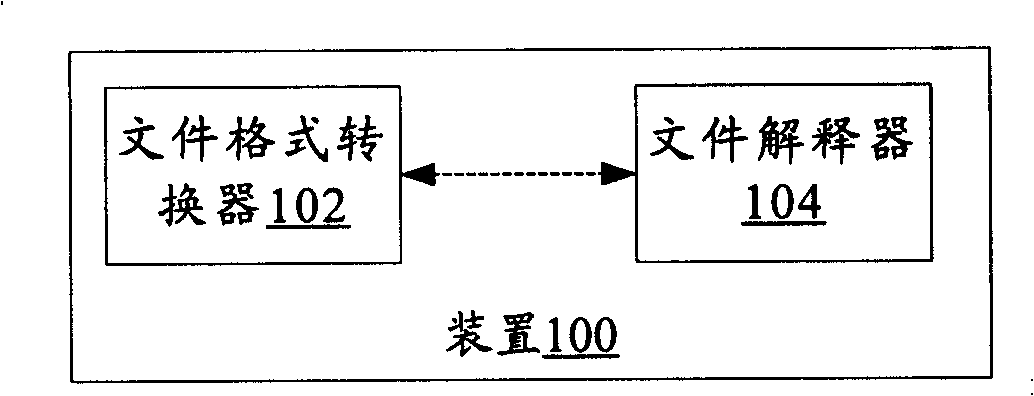
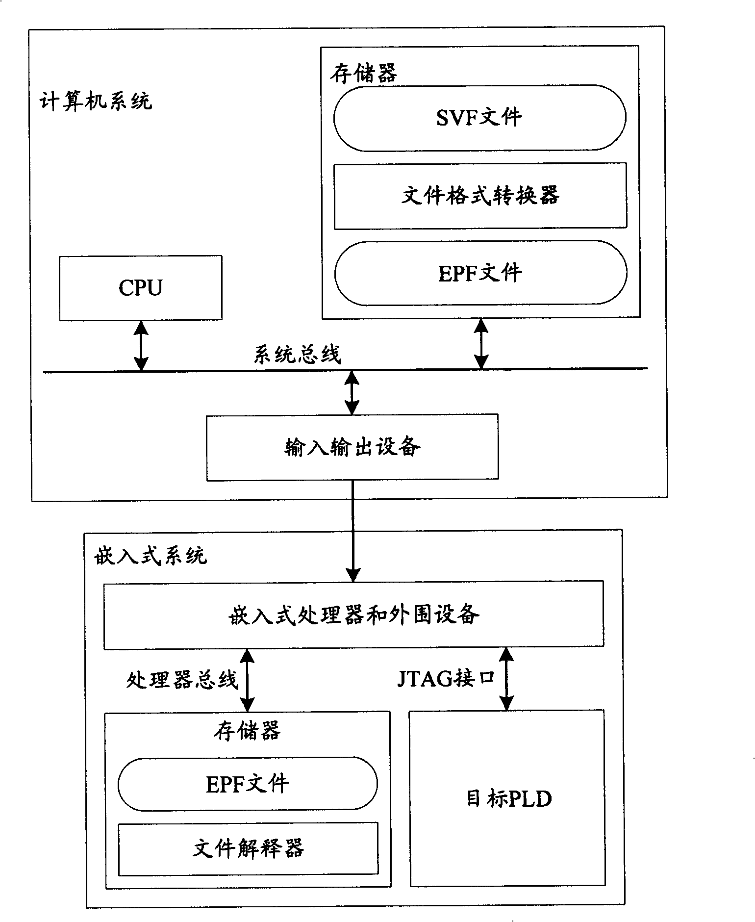
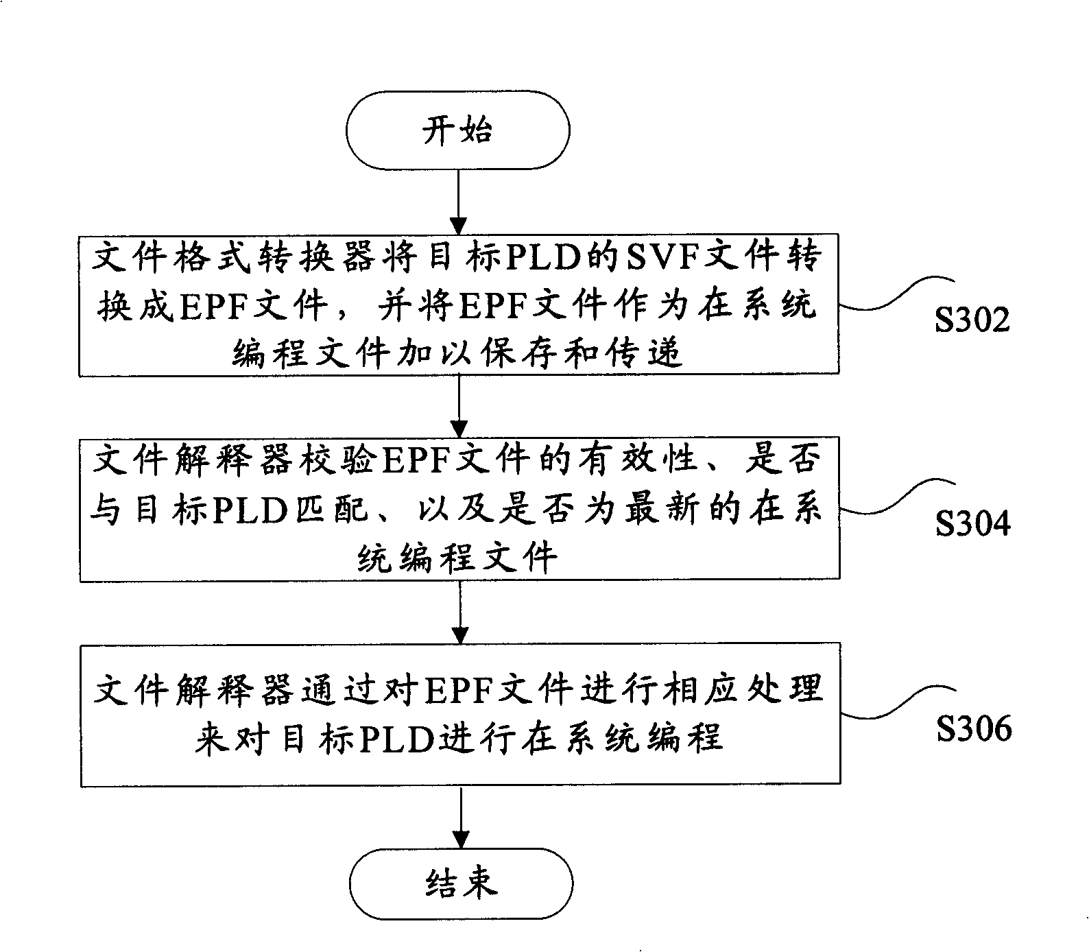
[0069] The following will combine Figure 5 The processing flow of the file format converter 102 will be described. Such as Figure 5 As shown, the processing of the file format converter 102 includes the following steps:

[0070] S1, open the SVF file of a target PLD, extract the instruction register length and various data register lengths of this PLD from SIR order, SDR order respectively;

[0071] S2, compare with the command register length and the data register length defined in their boundary scan description (BSD) files by all model PLDs, determine the model of the target PLD;

[0072] S3. If the SVF files of all target PLDs have been scanned, continue to S4, otherwise open the SVF file of the next target PLD in the daisy chain, and return to S1;

[0073] S4, process target PLD one by one, scan its SVF file;

[0074] S5. According to the instruction register length of all devices in the daisy chain and the position of the current target PLD in the daisy chain, calc...

example 2

[0099] The following will combine Figure 7 To describe the processing flow of the file interpreter 104. Such as Figure 7 As shown, the processing of file interpreter 104 includes the following steps:

[0100] S1. Perform CRC-16 calculation on the part of the EPF file other than the CRC-16 check information. If the calculation result is consistent with the CRC-16 check information in the EPF file, continue to execute S2, otherwise a CRC-16 check error will be prompted. , end the programming process;

[0101] S2, check the version information of the EPF file, if it matches the target PLD, continue to execute S3, otherwise it will prompt the file version verification error, and end the programming process;

[0102] S3, decompress the compressed data in the EPF file according to the Deflate algorithm, and restore the EPF programming data;

[0103] S4, in the EPF programming data, identify the command words represented by various symbol codes, according to

[0104] The "bit ...


PUM


Abstract

The invention provides an installment used to carry on the in-system programming for the programmable logical component, the equipment includes: a document format converter used to convert the serial vector format file of the goal programmable logic component to an embedded programming format file as the in-system programming file of the goal programmable logic component; and a file interpreter used to analyze the input embedded programming format file to produce programming information conforming to the IEEE1149.1, and a JTAG connection signal is driven according to the programming information to carry on the in-system programming of the goal programmable logic component. In addition, the invention also provides a method used to carry on the in-system programming for the programmable logical component. The following effects are achieved through the technical program of the invention: while retaining the superiority suitable for nearly all the present programmable logical component manufacturer component, solving the problems that the memory resources consumption is big, the error detection ability is weak, and each stage in the whole in-system programming process cannot be displayed and distinguished.

Description

technical field [0001] The present invention relates to the field of application of programmable integrated circuits, in particular, to a device and method for in-system programming (ISP: In System Programming) of a programmable logic device (PLD), which is especially suitable for storage resources and computing resources Occasions where the PLD online upgrade (on-line upgrade) function is provided in a limited embedded system. Background technique [0002] Programmable Logic Device (PLD) is a class of integrated circuits that contain programmable units, Electrically Programmable Logic Devices (EPLD), Complex Programmable Logic Devices (CPLD), and Field Programmable Gate Arrays (FPGA) are typical programmable Logic devices, they are widely used in various application fields of digital circuits. Using programmable logic devices, designers can realize large-scale digital logic circuits in limited printed circuit board (PCB) space, and can simplify the preparation of circuit b...

Claims


Application Information

Patent Timeline
Patent Type & Authority Applications(China)
IPC IPC(8): G06F9/45G01R31/3167
Inventor 曹兴国马立军黄燕荣林盛荣
Owner ZTE CORP
Why Eureka
Try Eureka