Method for restraining power grid single-phase short circuit current

A single-phase short circuit, power grid technology, applied in the field of power transmission and transformation, can solve the problems of weakening the electrical connection of the system, stability impact, and large investment.

Active Publication Date: 2008-09-17
STATE GRID JIANGSU ELECTRIC POWER CO ELECTRIC POWER RES INST +1
View PDF0 Cites 13 Cited by
  • Summary
  • Abstract
  • Description
  • Claims
  • Application Information

AI Technical Summary

Problems solved by technology

[0004] The first category is to replace the switch with a larger breaking capacity. The replacement of the switch may not affect the operation characteristics of the power grid. However, since the substation with excessive short-circuit current is generally a hub substation, there are a large number of switches that need to be replaced, and all primary equipment and grounding grids It also needs to be replaced, the investment is large, the construction period is long, and the power grid hub substation is in abnormal operation mode for a long time
[0005] The second category is to suppress the three-phase short-circuit current so as to reduce the single-phase short-circuit current. There are many such measures, including the partition operation of the 220kV power grid, the two-line lap connection at the 220kV exit of the 500kV substation, and the 220kV bus section of the 500kV substation or Separate operation is relatively convenient to implement in terms of measures, but they are all temporary measures to solve the short-circuit current, and these measures will weaken the electrical connection of the system and reduce the safety, reliability, flexibility and scale of power grid operation benefit
The use of high-impedance transformers can better suppress three-phase and single-phase short-circuit currents, but it al...

Method used


Image

  • Method for restraining power grid single-phase short circuit current
  • Method for restraining power grid single-phase short circuit current
  • Method for restraining power grid single-phase short circuit current

Examples


Embodiment Construction

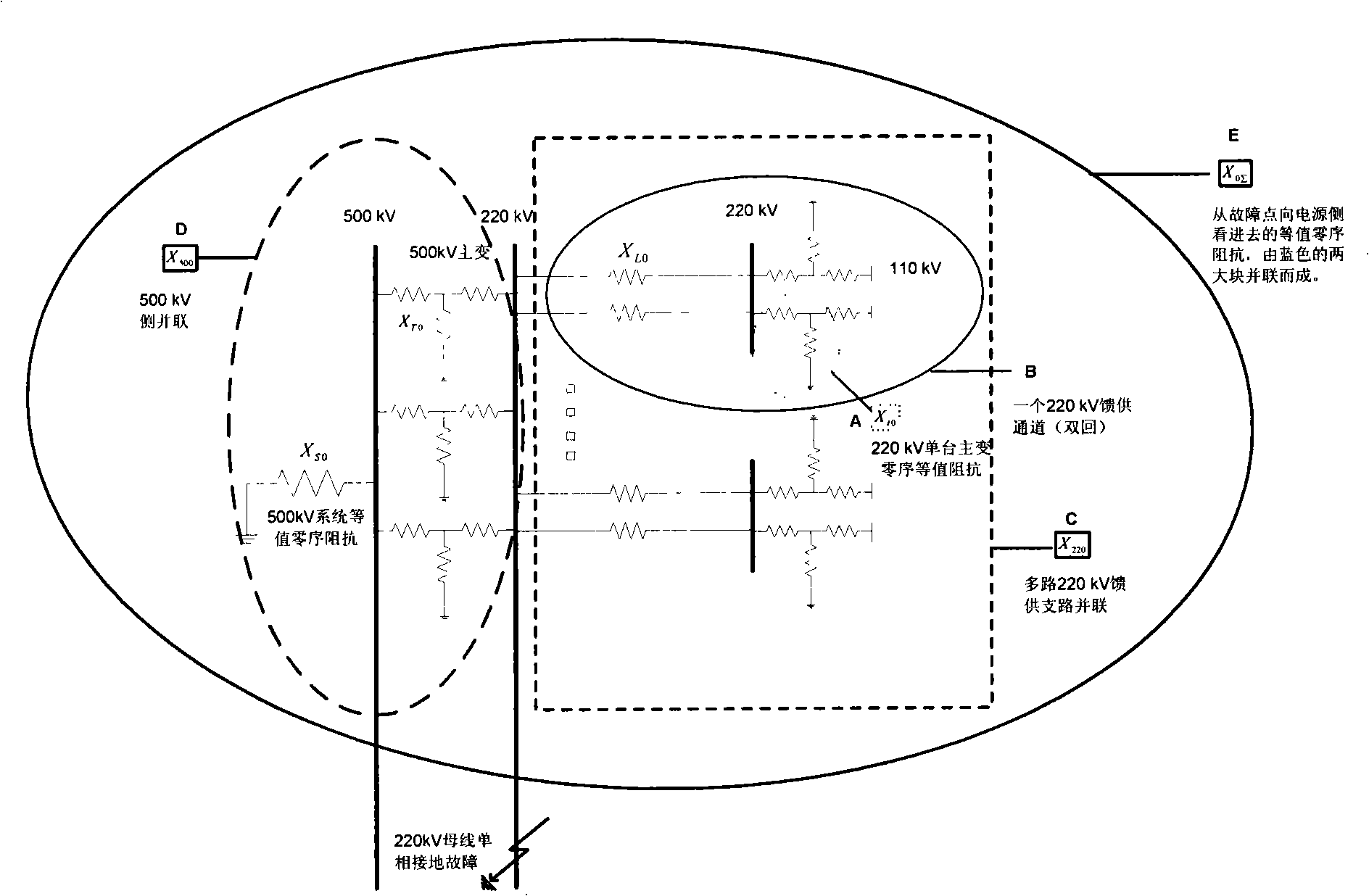
[0015] Grid-intensive areas have basically realized 500kV / 220kV layered and partitioned operation. Some partitions have one 500kV station with a 220kV power grid, and some partitions have two 500kV stations with a 220kV power grid. figure 1 It is a typical partition, that is, a zero-sequence network diagram of a 500kV station with a 220kV power grid.

[0016] (1) 220kV autotransformer replaced by non-autotransformer, X t0 / 2 becomes X t0 , figure 1 Part A is a single 220kV self-coupling variable zero-sequence impedance X t0 . Take a 120MVA transformer, the typical parameter is U hm = 9%, U hl = 31%, U ml =21%, based on 100MVA, calculate the high-voltage side impedance X 1 =0.079p.u., medium voltage side impedance X 2 =-0.004p.u., low voltage side impedance X 3 = 0.179 p.u. Two autotransformers in a 220kV station, then the equivalent zero-sequence impedance is X t0 / 2=0.179p.u., if both are non-autotransformers, only one main transformer needs to be grounded, so the ...


PUM


Abstract

The present invention provides a method of inhibiting 220kV side bus single-phase short circuit current of 500kV pivotal substation. An electric grid adopting mass autotransformers makes the more 220kV side bus single-phase short circuit current of 500kV pivotal substations larger than the three-phase short circuit current, and exceeding the rated breaking ability of the circuit breaker. Considering change the autotransformer to non-autotransformer to reduce the single-phase short circuit current, reducing the grounding branch of the zero-sequence grid essentially. According to the sequence diagrams principle analyse, changing autotransformer to the non-autotransformer in 500 kV substation has a larger impact to the 220kV bus single-phase short circuit current of the 500kV pivotal substation than changing the autotransformer to the non-autotransformer in the 220 kV substation, the practical example also proves the accuracy of the theoretical analysis. The method provides technical support for the limiting the grid single-phase short circuit current, enhancing the credibility of the grid operation.

Description

technical field [0001] The invention relates to a method for suppressing single-phase short-circuit current of a power grid. It belongs to the technical field of power transmission and transformation. Background technique [0002] With the rapid growth of power demand in Jiangsu, the scale of the power system is expanding day by day, the power supply and power grid are more dense, and the short-circuit current of the power grid continues to rise. According to the short-circuit current calculation of Jiangsu power grid in 2007-2008, the single-phase short-circuit current of the 220kV bus in some 500kV hub substations has exceeded the rated breaking capacity (50kA) of the circuit breaker, and the three-phase short-circuit current is also close to 50kA. When the single-phase ground short-circuit current exceeds the rated breaking capacity of the circuit breaker, the electromotive force and thermal stress of the short-circuit current will damage the circuit breaker and related ...

Claims


Application Information

Patent Timeline
IPC IPC(8): H02H7/26H02H9/02
Inventor 江林许扬周前魏旭陈久林李群
Owner STATE GRID JIANGSU ELECTRIC POWER CO ELECTRIC POWER RES INST
Why Eureka
Try Eureka