
Testing apparatus of multi-layer nano-film tunneling micro-gyroscope

A detection device and nano-membrane technology, which is applied in the direction of measuring device, gyro effect for speed measurement, gyroscope/steering sensing equipment, etc., can solve problems such as difficult to meet, precision drift, effective capacitance area limitation, etc.

Inactive Publication Date: 2008-09-24
ZHONGBEI UNIV
View PDF0 Cites 14 Cited by
  • Summary
  • Abstract
  • Description
  • Claims
  • Application Information

AI Technical Summary

Problems solved by technology

[0003] At present, the commonly used detection methods of micro-mechanical gyroscopes are capacitive and piezoresistive. The piezoresistive type is realized based on the principle of piezoresistive effect of highly doped silicon. Dependence, the bridge detection circuit composed of pressure-sensitive devices will also cause precision drift due to temperature changes. The improvement of capacitive precision is to increase the capacitance area. Due to the miniaturization of devices, the effective capacitance area has been greatly affected. limit
[0004] The attitude measurement of the micro-mechanical electronic gyroscope is completed by the head of the detection device, and its sensitivity and resolution are very important. Due to the miniaturization and integration of the gyroscope, the sensitive area of ​​the detection is reduced accordingly, so the detection The sensitivity, resolution and other indicators of gyroscopes have reached the limit state of sensitive area detection, which limits the further improvement of gyroscope detection accuracy, and it is difficult to meet the needs of modern military and civilian equipment. In this situation, it is necessary to develop high-tech A brand-new microelectromechanical gyroscope detection device that can break through the limit state

Method used


Image

  • Testing apparatus of multi-layer nano-film tunneling micro-gyroscope
  • Testing apparatus of multi-layer nano-film tunneling micro-gyroscope
  • Testing apparatus of multi-layer nano-film tunneling micro-gyroscope

Examples


Embodiment Construction

[0036] The present invention will be further described below in conjunction with accompanying drawing:

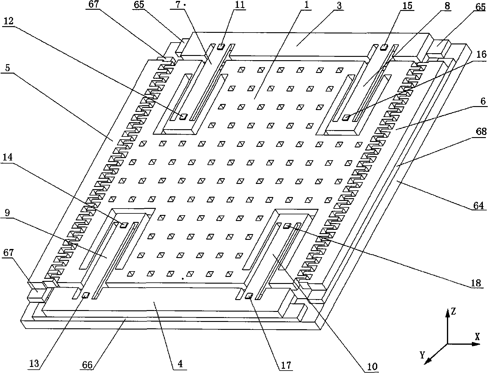
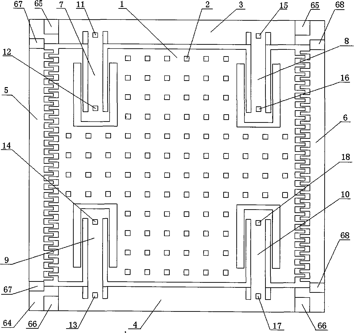
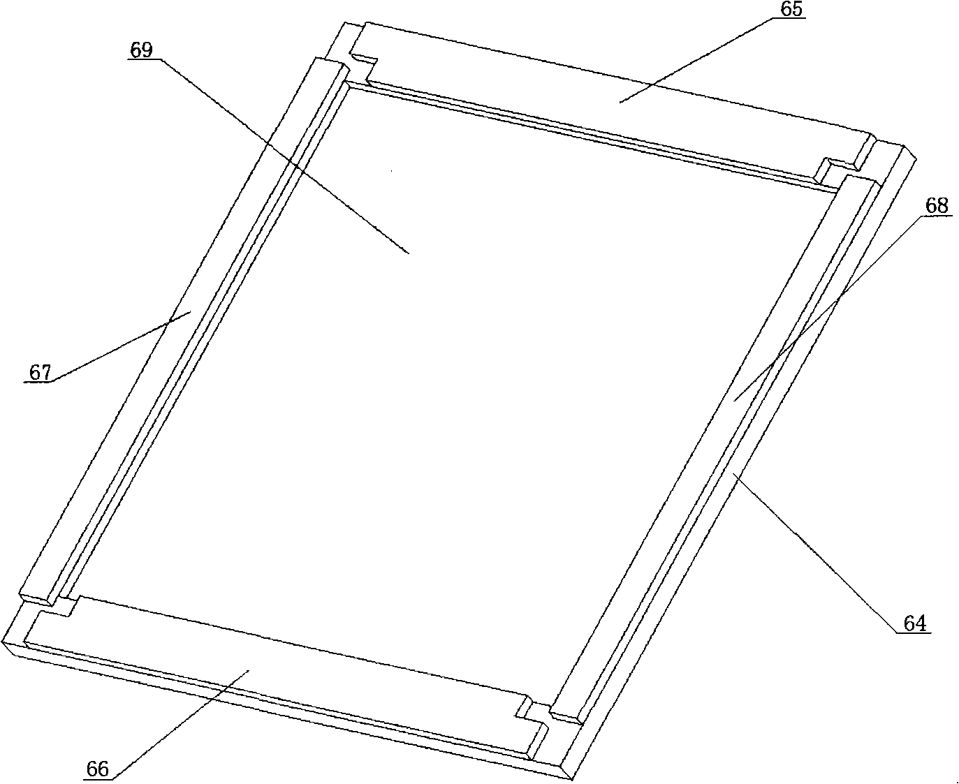
[0037] figure 1 , 2 As shown, it is an overall structure diagram, with a glass substrate 64 as a carrier, fixed electrode positive poles 65, 66, comb-tooth electrode negative poles 67, 68 are arranged on the front, rear, left and right parts, and the bottom groove 69 is in the middle. Inside 69 is the sensitive mass 1, with the sensitive mass 1 as the center, fixed comb teeth 5, 6 are arranged on the left and right, and are cross-connected with the comb teeth 19, 20 on the sensitive mass 1, and the front and rear fixed seats 3, 4 are connected with the The detection mechanisms 7, 8, 9, 10 are anastomosingly connected, and the damping holes 2 are 96 through-hole squares, which can also be designed as a circle or a rectangle as required, or 48, 72, or 120 can be set as required. It can be determined according to the application environment and damping coefficient.

[0038]...


PUM


Abstract

A detection device of a multi-layer nanometer film tunneling micro-gyroscope consists of a glass substrate, a fixed electrode cathode, a comb electrode anode, a sensitive mass block, a fixed seat, a fixed comb, a damping hole, a detection beam, a driving beam, a connecting block, a tunneling device, and a nano film, wherein a fixed seat and a comb are mounted on the sensitive mass block, the detection consists of the detection beam, the driving beam and the tunneling device, the tunneling device consists of a substrate, an insulating layer, an electrode and a nano film, the fixed electrode cathode and the comb electrode anode are mounted on the glass substrate, the damping hole comprises 96 square via holes, the tunneling device can form a multi-barrier pressure sensitive structure because of the nano film, and the sensitivity of the silicon piezoresistive pressure sensor can increased by 1-2 order of magnitude. The device has reasonable and compact structure, convenient detection, high detecting precision, high sensitivity and high resolution, which is not effected by temperature. Compared with prior art, the detection precision is increased by 2-3 times, the detection data is detailed, accurate and reliable.

Description

technical field [0001] The invention relates to a detection device of a multilayer nano-film tunneling gyroscope, which belongs to the technical field of measuring instruments and components of aviation aircraft. Background technique [0002] The micro-mechanical electronic gyroscope is a high-tech product developed in the 1990s. It is mainly used for attitude measurement and functional control of aerospace vehicles. It is one of the most important key devices that are indispensable for military and civilian aircraft. It has been highly valued by the world's aerospace science and technology field. [0003] At present, the commonly used detection methods of micro-mechanical gyroscopes are capacitive and piezoresistive. The piezoresistive type is realized based on the principle of piezoresistive effect of highly doped silicon. The pressure sensitive device formed by highly doped silicon has a strong temperature Dependence, the bridge detection circuit composed of pressure-sen...

Claims


Application Information

Patent Timeline
IPC IPC(8): G01C19/56G01P9/04G01C21/18G01C19/5656
Inventor 刘俊李孟委杜康石云波张斌珍杨卫李杰郭涛
Owner ZHONGBEI UNIV
Learn More