
Shaft sleeve structure of vehicle speed mileage sensor

A sensor and bushing technology, which is applied in the manufacturing field of automotive electronic components, can solve the problems of different machining accuracy, difficult to determine assembly tolerances, and wear of rotating shafts and bushings, so as to achieve ultra-low friction coefficient, convenient assembly and processing, The effect of simple manufacturing process

Inactive Publication Date: 2011-03-23
林金龙
View PDF0 Cites 0 Cited by
  • Summary
  • Abstract
  • Description
  • Claims
  • Application Information

AI Technical Summary

Problems solved by technology

Under high-speed operation and long-term working conditions of the car, the wear between the shaft and the bushing is serious, which affects the service life of the vehicle speed mileage sensor product. At the same time, since the shaft and the bushing are made of metal materials, heat will be generated in the working state , so that the vehicle speed mileage sensor operates at high temperature, thereby accelerating the aging of other electronic components and the oxidation and corrosion of other accessories, seriously affecting the quality and service life of the product
In addition, due to the high copper price in the current market, the copper bushing needs to be finished, which makes the labor cost of the single production material of the part relatively high. The coefficients are different, the machining accuracy is different, the assembly tolerance is difficult to determine, and the assembly process is relatively complicated, resulting in the phenomenon that the rotating shaft and the copper bushing are often stuck or the straight copper bushing and the aluminum housing of the speed mileage sensor are separated during the use of the product. Make the vehicle speed mileage sensor not function properly

Method used


Image

  • Shaft sleeve structure of vehicle speed mileage sensor
  • Shaft sleeve structure of vehicle speed mileage sensor

Examples


Embodiment Construction

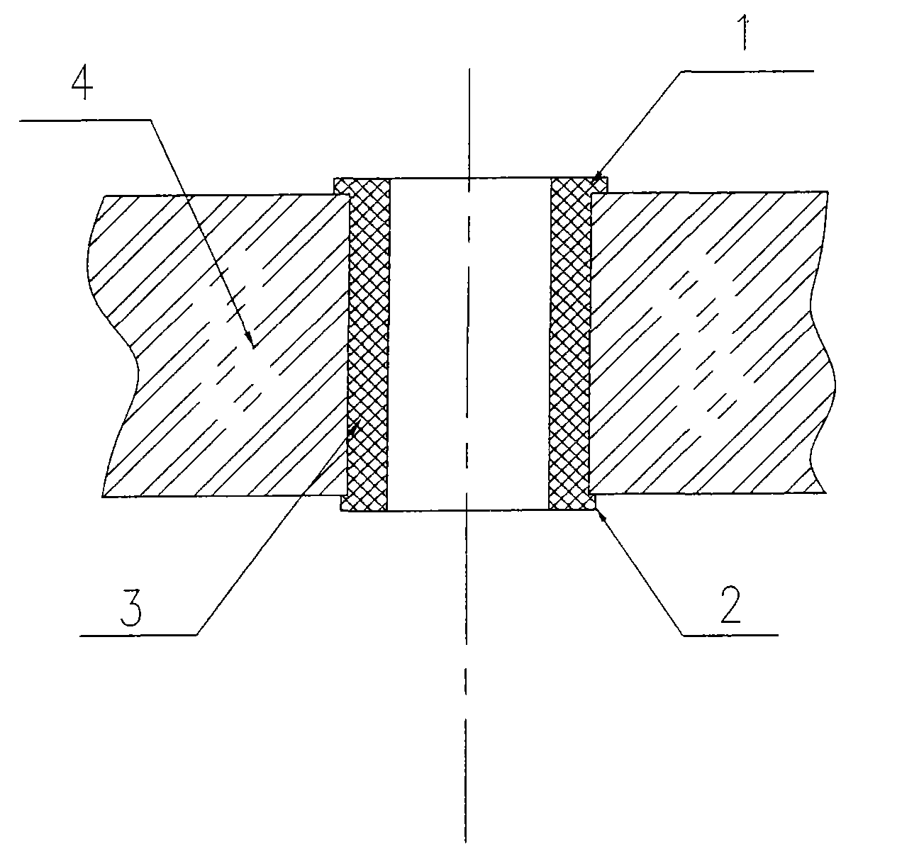
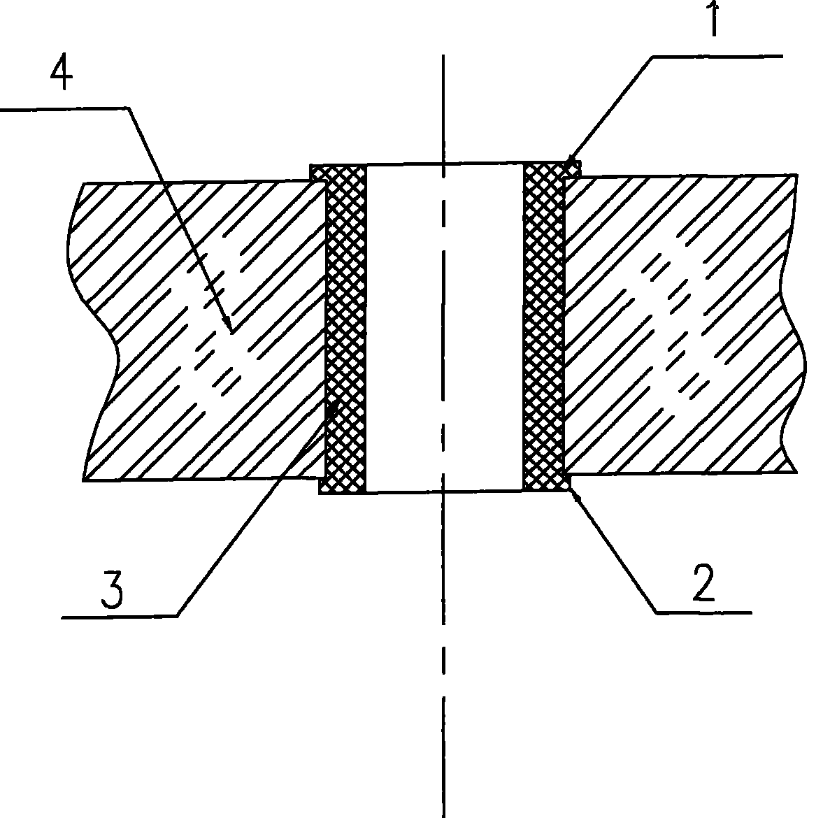
[0008] The present invention is mainly composed of a sensor aluminum shell 4, a shaft sleeve 3 placed in the sensor aluminum shell 4, etc., the material of the shaft sleeve 3 is plastic, preferably polyvinylidene fluoride plastic, and the upper part of the shaft sleeve 3 is provided with a convex edge 1 , the exposed part after the lower part is embedded in the sensor aluminum shell 4 is the extruded flanging structure 2 .

[0009] When used on the vehicle speed mileage sensor, the raw material is injection-molded into a shaft sleeve 3 of the required size, and the shaft sleeve 3 is pressed into the shaft hole of the sensor aluminum shell 4 with a press, and then reamed out with a reamer to match the diameter of the shaft. The hole diameter can be assembled with a rotating shaft. The invention is also applicable to all shaft sleeves with small force on the rotating grinding surface, light weight of the rotating parts and suitable temperature range.


PUM


Abstract

A shaft sleeve structure of a speed and mileage sensor belongs to the manufacture technical field of vehicle electronic parts and components. The structure essentially consists of a sensor aluminum shell (4), a shaft sleeve (3) arranged in the sensor aluminum shell (4), etc.; the shaft sleeve (3) is made of plastics, giving first priority to PVDF plastics; the upper part of the sleeve (3) is provided with a flange (1), and the lower part is inlaid into an exposed part behind the sensor aluminum shell (4) and is an extrusion flanging structure (2). The overall structure has reasonable design, simple manufacturing process, low cost, is convenient in assembly and processing, can inlaid and fix the plastic sleeve in the sensor aluminum shell so that the exposed part on the bottom is the extrusion flanging structure, according to changeable and recoverable characteristics of the plastics by external force; the plastic sleeve and the sensor aluminum shell are not easy to be separated; no heat is produced when the structure runs; a rotating shaft is not blocked or the sensor aluminum shell and the plastic sleeve are not separated, which can meet the utilization requirement for high-speedrotation of the rotating shaft.

Description

technical field [0001] The invention relates to a shaft sleeve structure of a vehicle speed mileage sensor, which belongs to the technical field of manufacturing electronic components for vehicles. Background technique [0002] The shaft sleeves of the existing vehicle speed and mileage sensors are all made of brass or bronze with good wear resistance to be processed into straight cylindrical shaft sleeves. Due to the working status of the vehicle speed and mileage sensors, the rotating shafts in the shaft sleeves need to rotate at high speed and send out. Signal. Under high-speed operation and long-term working conditions of the car, the wear between the shaft and the bushing is serious, which affects the service life of the vehicle speed mileage sensor product. At the same time, since the shaft and the bushing are made of metal materials, heat will be generated in the working state , so that the vehicle speed and mileage sensor operates at high temperature, thereby accele...

Claims


Application Information

Patent Timeline
Patent Type & Authority Patents(China)
IPC IPC(8): G01C23/00F16C33/20
Inventor 林金龙
Owner 林金龙
Learn More