Metal processing and molding method for reducing plastic resilience

A metal processing and plasticity technology, applied in the field of processing and forming of metal sheets, can solve the problems of large required load, difficult processing, and difficult to meet the yield strength and springback of high-strength metal sheets, so as to achieve easy processing and forming, and strong promotion. Value, high precision effect

Inactive Publication Date: 2008-10-01
HARBIN UNIV OF SCI & TECH
View PDF0 Cites 19 Cited by
  • Summary
  • Abstract
  • Description
  • Claims
  • Application Information

AI Technical Summary

Problems solved by technology

[0003] The purpose of the present invention is to provide a metal processing and forming method that reduces plastic springback, so as to solve the problems that it is difficult to meet the fo

Method used


Image

  • Metal processing and molding method for reducing plastic resilience
  • Metal processing and molding method for reducing plastic resilience
  • Metal processing and molding method for reducing plastic resilience

Examples


specific Embodiment approach 1

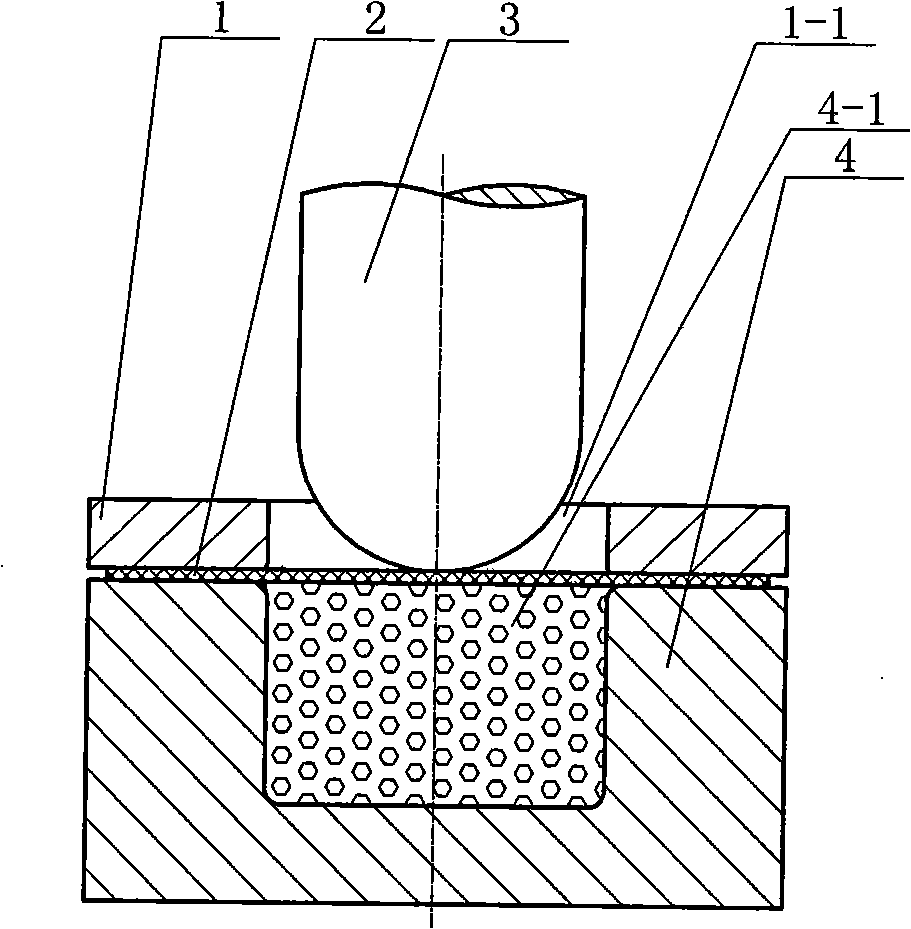
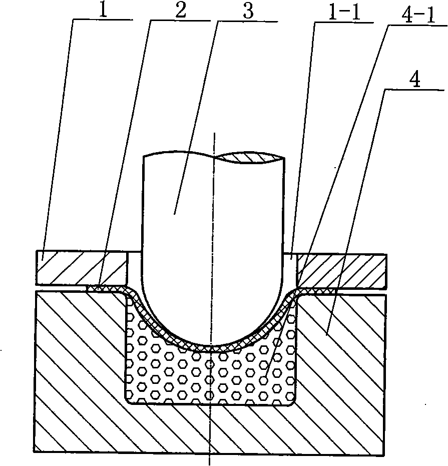
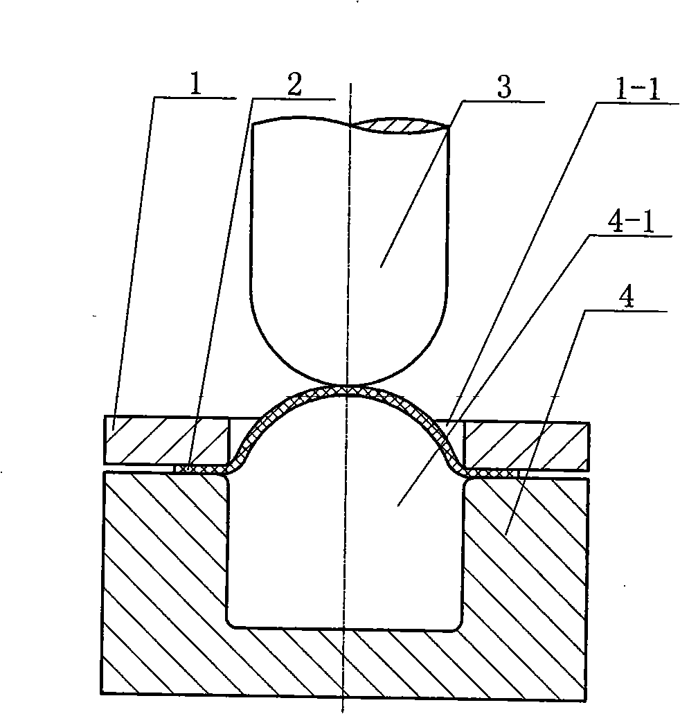
[0006] Specific implementation mode one: combine figure 1 - Fig. 5 illustrates this embodiment, and this embodiment is completed by the following steps: one, the sheet material 2 is placed on the die 4; The mold cavity 1-1 of the side ring 1 is coaxial with the concave mold cavity 4-1 of the die 4 and has the same aperture; 3. The punch 3 moves downward to apply pressure, and the sheet material 2 is deformed and flows into the concave mold cavity 4-1; 4. Remove the punch 3; 5. Remove the blank holder 1; 6. Place the sheet 2 on the die 4 in reverse; 7. Place the blank holder 1 on the sheet 2 and apply the blankholder Force, the mold cavity 1-1 of blank holder 1 is coaxial with the concave mold cavity 4-1 of die 4; Compared with the deformation in the original pre-strained direction, the elastic limit (yield limit) of the metal deformed in one direction is significantly lower when it is deformed in the opposite direction. This phenomenon is the Bauschinger effect of the metal. ...

specific Embodiment approach 2

[0007] Specific implementation mode two: combination figure 1 and figure 2 Describe this embodiment, the difference between this embodiment and specific embodiment 1 is: sand is provided in the concave mold 4 in step 1-step 5. First put a certain amount of sand in the concave mold cavity; place the blank on the concave mold; place the blank holder on the blank and apply blankholder force; the punch moves down to apply pressure, and the blank deforms and flows into the cavity. In the cavity of the concave mold; remove the punch and blank holder; pour out the sand in the cavity of the concave mold; place the sheet on the die in reverse; place the blank holder on the sheet and apply blankholder force ; The punch moves down to apply pressure, and the sheet deforms and flows into the cavity of the concave model. Due to the back pressure of the sand during the initial deep drawing, the thinning of the sheet metal during preforming is small, so the formed parts have good surface f...

specific Embodiment approach 3

[0008] Specific implementation mode three: In step one of this implementation mode, the sheet material 2 is superhard aluminum alloy or titanium alloy.


PUM


Abstract

The invention discloses a metal processing and molding method that lowers plastic resilience and solves the problems that the stamping and molding process of high-intensity metal sheets is hard to satisfy molding requirements, needs large load and difficult processing due to the larger yield stress and resilience. A plate (2) is placed on a cavity die (4); a stamping ring (1) is placed on the plate (2) and stamping force is exerted; a punch (3) is moved downward to exert force, and the plate (2) is deformed and flows into a die space (4-1) of the cavity die; the punch (3) is removed; the stamping ring (1) is removed; the plate (2) is oppositely placed on the cavity die (4); the stamping ring (1) is placed on the plate (2) and the stamping force is exerted; the punch (3) is moved downward to exert force, and the plate (2) is deformed and flows into the die space (4-1) of the cavity die. The metal processing and molding method lowers the yield stress of the high-intensity metal sheets, and has the advantages of easy processing and molding, reasonable design, reliable working, remarkable effect, simple and convenient operation, easy implementation, high precision and stronger generalization value.

Description

technical field [0001] The invention relates to a method for processing and forming metal plates. Background technique [0002] At present, automobile panels have gradually adopted high-strength steel plates with a yield strength lower limit of 275-460 MPa to replace the original soft steel plates with a yield strength below 270 MPa. Due to the increased strength, the thickness of the steel plate can be reduced according to the principle of equal-strength conversion. Can greatly reduce the total amount of steel. The main advantages of using high-strength steel sheets for automobile sheets are: the safety and dent resistance of automobiles can be improved due to the increase in material strength; In the conversion of high-strength steel plates, there are also problems in processing and forming due to the increase in material strength and the decrease in mechanical properties. Wrinkling, cracking and springback are the three most common defects in the stamping and forming pro...

Claims


Application Information

Patent Timeline
IPC IPC(8): B21D22/04
Inventor 李峰李大勇刘晓晶
Owner HARBIN UNIV OF SCI & TECH
Why Eureka
Try Eureka