Wave filter circuit

A filter circuit and filter capacitor technology, applied in electrical components, output power conversion devices, conversion equipment with intermediate conversion to AC, etc., can solve the problems of filter waste, large and expensive filters, etc., to reduce losses, Reduce the effect of high-frequency filtering and enhance the effect of suppression

Active Publication Date: 2008-10-01
VERTIV CORP
View PDF0 Cites 13 Cited by
  • Summary
  • Abstract
  • Description
  • Claims
  • Application Information

AI Technical Summary

Problems solved by technology

If you simply enhance the filter to suppress the frequency point, then, for other frequency points, such a strong filter is really a waste, if it c

Method used


Image

  • Wave filter circuit
  • Wave filter circuit
  • Wave filter circuit

Examples


Example Embodiment

Specific implementation mode one

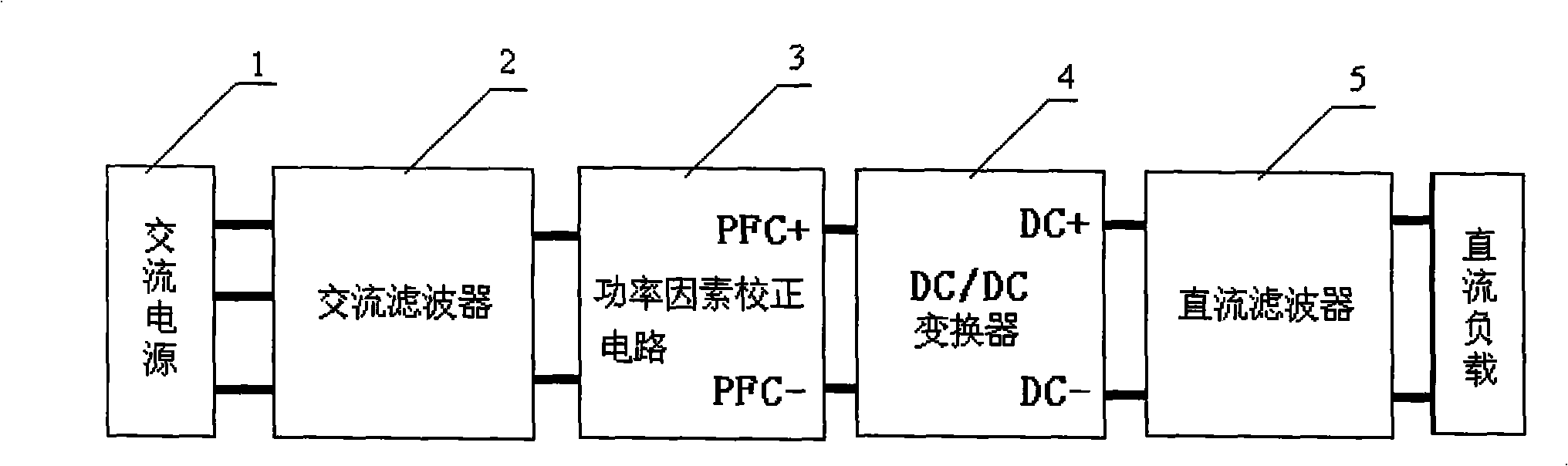
[0043] image 3 The switching power supply shown includes an AC power source 1 , an AC filter 2 , a power factor correction circuit (PFC) 3 , a DC / DC converter 4 and a DC filter 5 . The AC filter 2 is connected between the AC power source 1 and the power factor correction circuit 3 , and the DC / DC converter 4 is connected between the power factor correction circuit 3 and the DC filter 5 .

[0044] Figure 4a Shown is the DC / DC converter in the switching power supply, the converter adopts LLC topology, the full-load switching frequency is set to 220KHZ, and frequency modulation control. It includes: two power MOSFET switch tubes Q1 and Q2, LLC resonant capacitor Cr, LLC resonant inductance Lr, excitation inductance Lm, center-tapped transformer primary winding np, transformer secondary winding ns, half-bridge full-wave rectifier diodes D1 and D2 , the output filter capacitor Cf, and the Y capacitor CY1 (220nF) connected to the DC side DC-. ...

Example Embodiment

Specific implementation mode two

[0047] Figure 5a and Figure 4a The DC / DC converter differs in that, Figure 5a The shown DC / DC converter is connected with a Y capacitor CY2 (4.7nF) on its high-voltage DC side (that is, PFC-). Figure 5b It is a DC / DC converter adopting the LC resonant structure of the present invention, in which a resonant inductor LY2 (110 μH) is connected in series at one end of the capacitor CY2, and the other end of the resonant inductor LY2 is grounded, between the other end of the capacitor CY2 and the grounding end of the resonant inductor LY1 An auxiliary capacitor CY2' (1nF) is also connected in parallel.

[0048] In this embodiment, the common-mode conduction disturbance is handled by connecting a resonant inductor LY2 in series with the Y-capacitor CY2 (capacitor to ground, used for common-mode filtering, not necessarily marked with a Y-capacitor) to create a resonance point, that is, the The fundamental conduction disturbance frequency poin...

Example Embodiment

Specific implementation mode three

[0050] Figure 6a and Figure 4a The DC / DC converter differs in that, Figure 6a The shown DC / DC converter has three output filter capacitors Cf1~Cf3 (both 2.2μF) connected in parallel between its DC side power lines. Figure 6b It is a DC / DC converter adopting the LC resonant structure of the present invention, and a resonant inductance LX1 (0.24 μH) is connected in series with the capacitor Cf3 dealing with differential mode conduction disturbance.

[0051] In this embodiment, the processing method for differential mode conduction disturbance is to connect a resonant inductor LX1 in series with the differential mode capacitor Cf3 (capacitance between power lines, non-ground capacitor, for differential mode filtering, not necessarily marked with X capacitance), Create a resonance point, that is, the frequency point of the fundamental frequency conduction disturbance of the converter. The reactance of the LC resonance structure at this fr...


PUM


Abstract

The present invention discloses a wave filter circuit which comprises a filtering capacitor or filtering inductor, and a resonance inductor which is connected with the filtering capacitor in series to form a LC series circuit, or a resonance capacitor which is connected with the filtering inductor in parallel to form a LC parallel circuit. The control of the filtering capacitor/inductor to a single frequency point signal is reinforced through the LC series/parallel connection. The invention also discloses a switch power source which adopts the wave filter circuit. The switch power source comprises a capacitor or an inductor which can process the transmitting interference. At least one in the capacitors is in-series connected with a resonance inductor to form a LC series circuit. Or at least one in the inductors is in-parallel connected with a resonance capacitor to form a LC parallel circuit. The control of the capacitor/inductor to transmitting interference on a single frequency point is reinforced through the LC series/parallel resonance. The wave filterer circuit of the invention has an advantage of simple structure and can effectively process the stronger signal interference on a single frequency point.

Description

technical field [0001] The invention relates to a device for processing electromagnetic interference, in particular to a filter circuit for processing strong interference at a single frequency point by using LC resonance. Background technique [0002] With the development of electronic technology, the requirements for electromagnetic compatibility (EMC) in communication and other fields are becoming more and more stringent, and the requirements for the anti-electromagnetic interference ability of electronic circuits are also increasing accordingly. Existing filters are relatively effective in eliminating signal noise interference, but there are still deficiencies. For example, with the miniaturization of switching power supplies and the continuous improvement of power density, an LLC resonant direct current / direct current (DC / DC) converter emerges at the historic moment. The circuit has a characteristic: its fundamental frequency conduction disturbance is particularly stron...

Claims


Application Information

Patent Timeline
IPC IPC(8): H02M1/12H02M1/14H02M3/28
Inventor 朱春辉甘松柏潘诗风黄庆义
Owner VERTIV CORP
Why Eureka
Try Eureka