Power supply control apparatus for discharging processor
A technology of power control device and electric discharge machine, which is applied in electric machining equipment, metal machining equipment, circuits, etc., can solve the problems of discharge detection output drop, etc., and achieve the effect of accurate control, accurate discharge pulse and intermittent time
- Summary
- Abstract
- Description
- Claims
- Application Information
AI Technical Summary
Problems solved by technology
Method used
Image

Examples
Embodiment approach 1
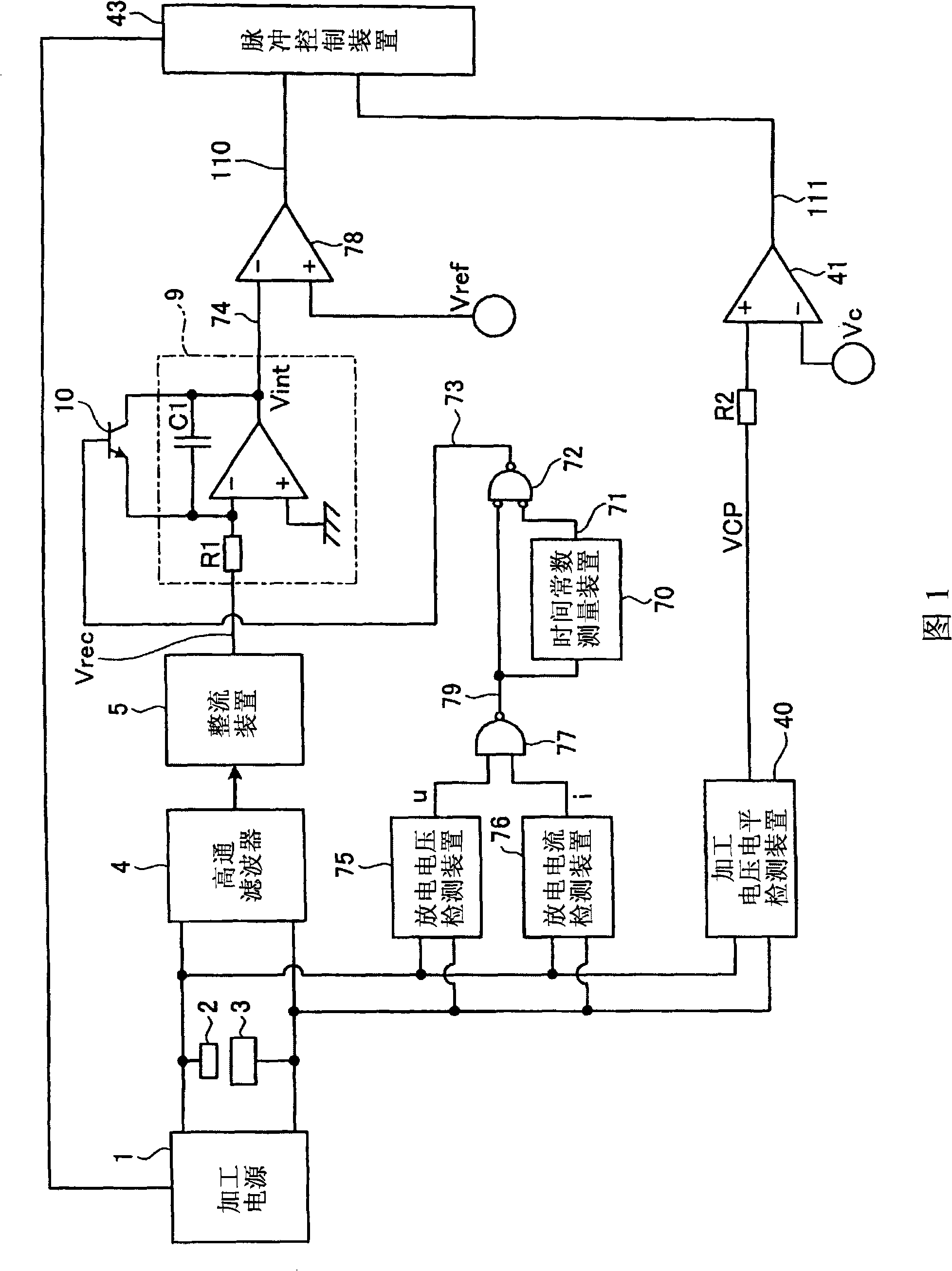
[0056] 1 is a schematic circuit diagram of main parts of a power supply control device for an electrical discharge machine according to Embodiment 1 of the present invention. In the drawing, a pulse-shaped discharge voltage is supplied to the machining gap between the electrode 2 and the workpiece 3 of the electric discharge machine. The high-pass filter 4 extracts high-frequency components of the discharge voltage. The rectification device 5 rectifies the high-frequency components extracted by the high-pass filter 4 to output an output signal Vrec. The discharge voltage detection device 75 detects the discharge voltage in the machining gap between the electrode 2 and the workpiece 3 . The discharge current detection device 76 detects the discharge current in the machining gap between the electrode 2 and the workpiece 3 .
[0057] The output signal u of the discharge voltage detection device 75 and the output signal i of the discharge current detection device 76 are input to...
Embodiment approach 2
[0072] Figure 5 It is a functional block diagram showing main parts of the power supply control device of the electric discharge machine according to Embodiment 2 of the present invention, and a part thereof is drawn as a circuit diagram. exist Figure 5 In , the machining gap is formed by the electrode 2 and the workpiece 3 . A pulse-shaped discharge voltage is supplied from the machining power source 1 to the machining gap. The high-pass filter 4 detects high-frequency components of the discharge voltage. The rectification device 5 rectifies the high-frequency components from the high-pass filter 4 . The rectified output signal is output from the rectifying device 5 . The discharge detection device 23 detects a discharge voltage and a discharge current in a machining gap between the electrode 2 and the workpiece 3 . Using the output of the discharge detection device 23, the integrating circuit 9 is reset, and the timer 24 is started. A short-circuit detection device 2...
Embodiment approach 3
[0088] Figure 9It is a functional block diagram showing main parts of the power supply control device of the electric discharge machine according to Embodiment 3 of the present invention, and a part thereof is drawn as a circuit diagram. for with Figure 5 The same or corresponding parts of the electric discharge machine power supply control device according to the second embodiment shown are given the same reference numerals, and description thereof will be omitted. In the power control device of this embodiment, in Figure 5 In addition to the power supply control device according to Embodiment 2 shown, a pulse cutoff rate calculation means (pulse cutoff rate calculation means) 50 is provided.
[0089] The average pause time calculation means (average pause time calculation means) 45 obtains the average value of the discharge pulse pause times which are controlled by the pulse control means (pulse control means) 43 . The pulse cut-off rate calculation means (pulse cut-of...
PUM
| Property | Measurement | Unit |
|---|---|---|
| Diameter | aaaaa | aaaaa |
Abstract
Description
Claims
Application Information
 - R&D
- Intellectual Property
- Life Sciences
- Materials
- Tech Scout
- Unparalleled Data Quality
- Higher Quality Content
- 60% Fewer Hallucinations
Browse by: Latest US Patents, China's latest patents, Technical Efficacy Thesaurus, Application Domain, Technology Topic, Popular Technical Reports.
© 2025 PatSnap. All rights reserved.Legal|Privacy policy|Modern Slavery Act Transparency Statement|Sitemap|About US| Contact US: help@patsnap.com