Car white vehicle body structure static angular rigidity testing system and testing method thereof
A testing system and body-in-white technology, which is applied in the field of automobile manufacturing, can solve the problems of applying for patents for technical solutions or being reported in the literature, and achieves the effects of simple operation, good versatility and improved efficiency.
- Summary
- Abstract
- Description
- Claims
- Application Information
AI Technical Summary
Problems solved by technology
Method used
Image
Examples
Embodiment 1
[0063] This embodiment solves the problems of loading, data collection and data processing in the test system.
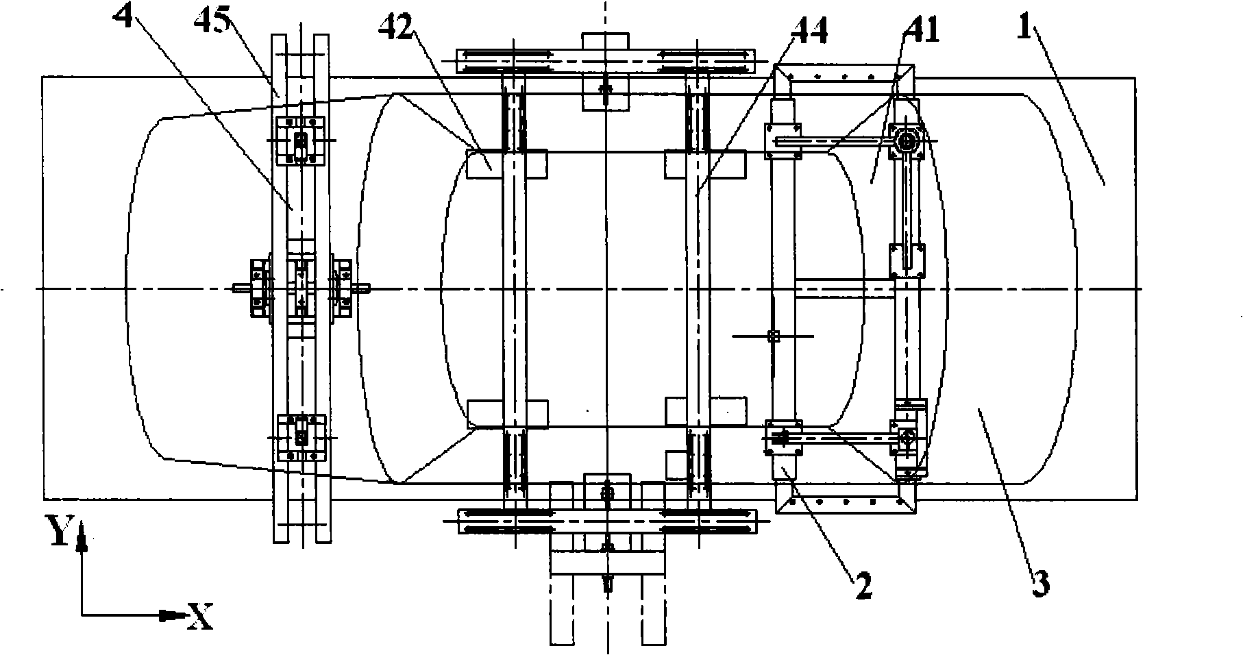
[0064] The test system is provided with a computer control unit, and the servo loading device 42 is connected with the computer control unit through a signal line; the data collection and processing system is provided with sensors and signal lines connected with the computer control unit.
[0065] Before the test, according to different models and specific test requirements, set the test program and store it in the computer control unit. During the test, the computer control unit sends a loading instruction, and the bending stiffness loading device 44 and the torsional stiffness loading device 45 perform different loadings; the loading force is converted into an electrical signal by the force sensor and sent to the computer control unit; at the same time, the value of the deformation amount corresponding to the test body 3 is also converted into an electrical signal...
Embodiment 2
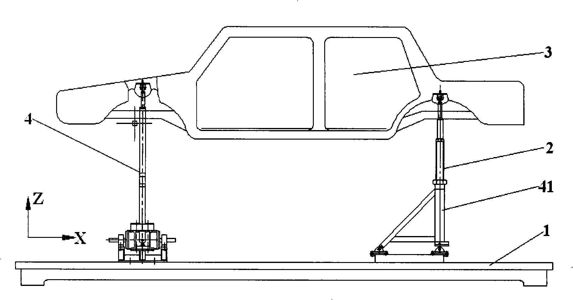
[0068] In this embodiment, the front support assembly 4 can be used not only as the restraining device 41 but also as the torsional rigidity loading device.
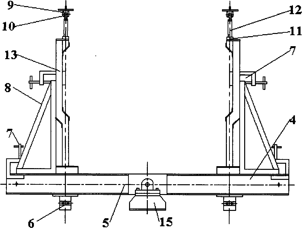
[0069] Such as image 3 , Figure 4 , Figure 5 As shown, the front support assembly 4 is arranged on the front end of the test vehicle body 3, on which a front support turntable 15, a front support arm 5, a front support column 13 with joint bearings at both ends and a front support column are arranged. Seat joint bearing 10, front support slide assembly 14, front support lock nut 11, front support connecting rod 12, etc.
[0070] The structure of the front support assembly 4 is as follows: the bottom surface of the front support turntable 15 is fastened to the test bench floor 1, and the front support arm 5 passes through the center of its length from the front The support turntable 15 is supported, and the connection between the front support turntable 15 and the front support arm 5 is provided with a rotating disk...
Embodiment 3
[0074] This embodiment is a structure in which the front support assembly 4 is used as a part of the restraint device 41 .
[0075] Such as image 3 with Figure 4 As shown, the rotation directions of the front support joint bearings 10 on the two ends of the respective front support columns 13 are perpendicular to each other, and the axis of the front support joint bearings 10 at the upper end is parallel to the longitudinal centerline of the vehicle body.
[0076] The purpose of this structure is to make the front support assembly 4 have a certain degree of flexibility during the stress and deformation process of the test vehicle body 3, without affecting the free deformation of the vehicle, that is to say, the stiffness of the front support assembly 4 itself Does not affect the test of the test body 3.
PUM
 Abstract
Description
Claims
Application Information
 - R&D
- Intellectual Property
- Life Sciences
- Materials
- Tech Scout
- Unparalleled Data Quality
- Higher Quality Content
- 60% Fewer Hallucinations
Browse by: Latest US Patents, China's latest patents, Technical Efficacy Thesaurus, Application Domain, Technology Topic, Popular Technical Reports.
© 2025 PatSnap. All rights reserved.Legal|Privacy policy|Modern Slavery Act Transparency Statement|Sitemap|About US| Contact US: help@patsnap.com


