Numerical control bending machine and bending method thereof

A technology of bending machine and numerical control device, applied in the direction of digital control, mechanical equipment, electrical program control, etc., can solve the problems of low work efficiency, failure to improve work efficiency, waste, etc., achieve simple processing, improve work efficiency and processing quality, and save materials Effect

Inactive Publication Date: 2008-10-15
湖南电器研究所
View PDF0 Cites 24 Cited by
  • Summary
  • Abstract
  • Description
  • Claims
  • Application Information

AI Technical Summary

Problems solved by technology

If a rough calculation is made, the error is too large, often resulting in waste
[0004] 2. In order to ensure success when cutting the material, it is often necessary to lengthen it appropriately, and then cut the tail after bending, resulting in waste of tailings
[0005] 3. When bending, the size depends on visual inspection. The bending angle often needs to be adjusted repeatedly to meet the requirements. Not only is the work efficiency low, but the internal structure and surface quality of the copper bar are easily damaged when the angle is adjusted repeatedly.
[0006] 4. For a batch of copper bars of the same size, the work efficiency cannot be improved due to the increase in batches, and the shape after processing is not uniform

Method used


Image

  • Numerical control bending machine and bending method thereof
  • Numerical control bending machine and bending method thereof
  • Numerical control bending machine and bending method thereof

Examples


Embodiment Construction

[0031] The present invention is further explained as follows with reference to accompanying drawing in conjunction with specific embodiment:

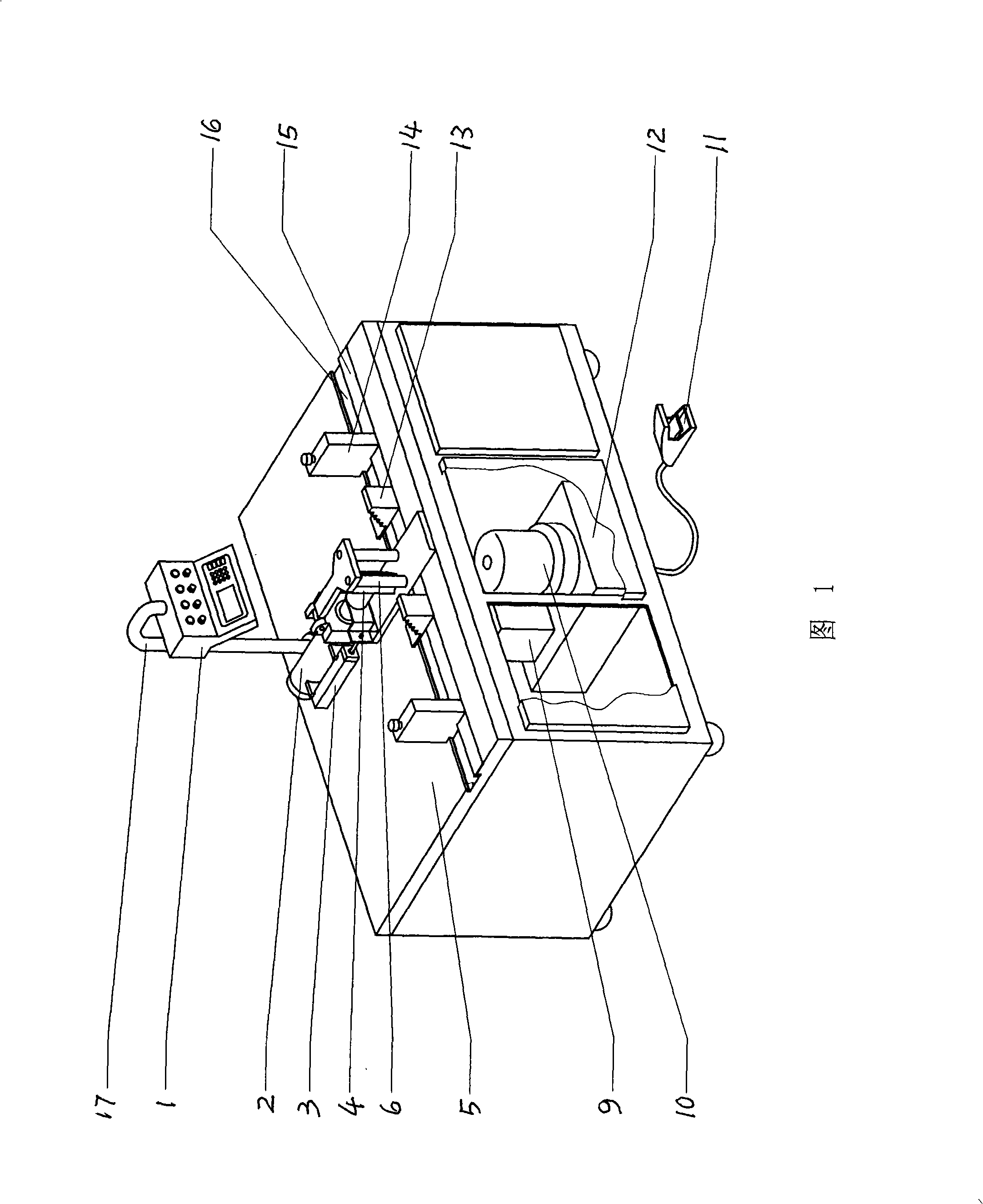
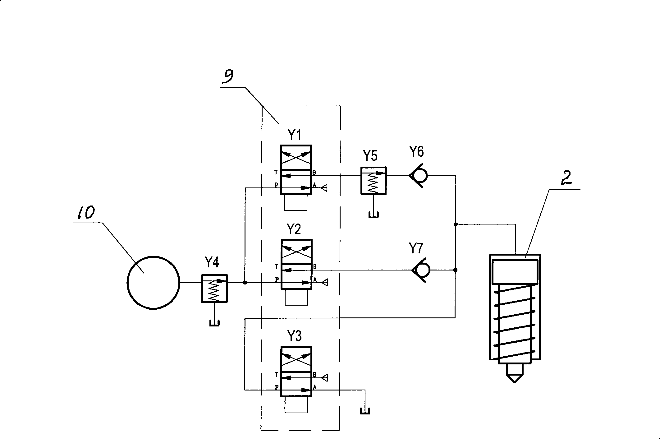
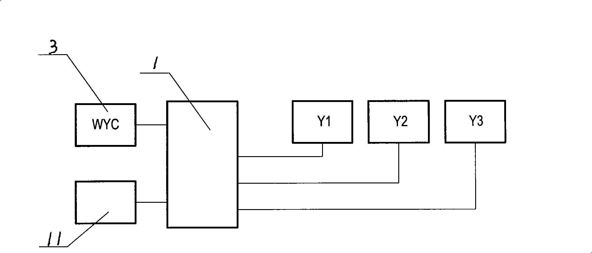
[0032] A numerically controlled bending machine, whose structure is shown in the attached drawing 1, is mainly composed of a frame platen 5, a pressing head 4, a positioning guide column 6, a numerically controlled device 1 and a hydraulic transmission device. The top pressure head 4 and two positioning guide columns 6 are installed on the frame platen 5, the top pressure head 4 is connected with the oil cylinder 2, and the oil pump 10 is installed under the frame platen 5, and the oil pump 10 passes through the solenoid valve group 9 and the pressure limiting valve Y4, Y5, one-way valves Y6, Y7 and oil tank I2 are connected by oil pipe and oil cylinder 2 to form a hydraulic transmission device. The solenoid valve group 9 includes three solenoid valves Y1, Y2, Y3, and the hydraulic transmission device is electrically connected with the ...


PUM


Abstract

The invention relates to a numerical control bending machine, a top pressing head and two positioning guide pillars are arranged on a table board of a machine rack, the top pressing head is connected with an oil cylinder, an oil pump is arranged below the table board of the machine rack, the oil pump is connected with an oil pipe and the oil cylinder by a valve to compose a hydraulic transmitting device; an electromagnetic valve in the hydraulic transmitting device is electrically connected with a numerical control device, and the numerical control device is composed of a power supply circuit, a control circuit, a drive circuit and an operation circuit. The method of adopting the machine for bending a copper bar is that a software program is inputted in the numerical control device, the copper bar is processed and bent by a top pressure stroke determined by the calculation of the input parameters according to the program; the input parameters are: the thickness of the copper bar to be bent; the horizontal distance between the copper bar to be bent and the lap surface of an upper mother copper bar and a lower mother copper bar; the linear distance between the corresponding edges of the upper mother copper bar and the lower mother copper bar; the lap length between the copper bar to be bent and the upper and lower mother copper bars; and the distances from the upper and the lower ends of the copper bar to be bent to the upper mother copper bar and the lower mother copper bar. The numerical control bending machine has the advantages that: the copper bar is processed and bent precisely, so that the numerical control bending machine has no tailing and can save the materials; the processing is simple and convenient, the working efficiency and the processing quality are improved.

Description

Technical field: [0001] The invention relates to a bending machine and a bending method, in particular to a numerical control bending machine and a bending method which can automatically calculate and control the bending angle after inputting the installation size of a copper bar. Background technique: [0002] At present, in the domestic complete set of electrical appliances industry, the well-known bronze row bending processing equipment is a simple hydraulic bending machine, which is mainly composed of an oil pump, an oil cylinder, a top pressure head and a positioning guide column. For the basic structure, see Figure 7 . The existing bending method is to use this simple hydraulic bending machine. Manually operate the hydraulic switch to control the hydraulic device to push the top pressure head to test the bending copper bar. Each copper bar needs to be adjusted repeatedly to achieve the expected bending. The defect of the existing equipment and its methods is that the ...

Claims


Application Information

Patent Timeline
Patent Type & Authority Applications(China)
IPC IPC(8): B21D7/12B21D7/06G05B19/18F15B21/02
Inventor 朱健龚光辉黄乐陈可夫李林冯浪平
Owner 湖南电器研究所
Why Eureka
Try Eureka