Low delivery head great specific gravity fluid delivery pump

A liquid transfer pump, low head technology, used in special fluid pumps, liquid fuel engines, pumps, etc.

Inactive Publication Date: 2008-10-15
CINF ENG CO LTD
View PDF0 Cites 7 Cited by
  • Summary
  • Abstract
  • Description
  • Claims
  • Application Information

AI Technical Summary

Problems solved by technology

[0017] 10. Inlet and outlet diameter

Method used

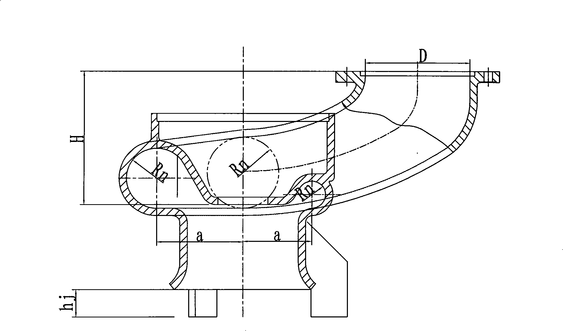
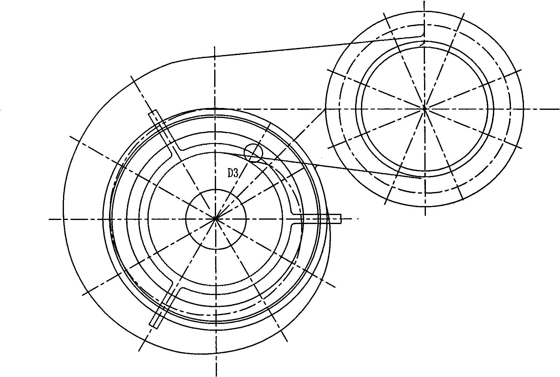
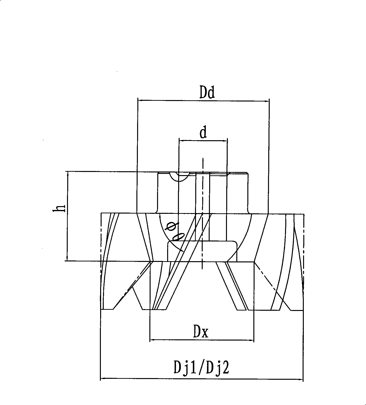

Image

  • Low delivery head great specific gravity fluid delivery pump
  • Low delivery head great specific gravity fluid delivery pump
  • Low delivery head great specific gravity fluid delivery pump

Examples


Embodiment

[0144] The process configuration design requires double-pipe transportation, the transportation capacity is 5100t / h, the head is 2,2m, (the specific gravity of lead liquid is 10.5t / m 3 ).

[0145] (1) Overall scheme design (determination of main parameters)

[0146] 1. Calculate the motor power N according to the pump capacity:

[0147] No=Q*γ*H / (102*η)(KW)

[0148] In the formula: Q——Single-pipe flow rate,

[0149] γ=10500(kg / m 3 )

[0150] Q=5100 / (2*10.5*3600)=0.0675(m 3 / s)

[0151] H=2.2m

[0152] η=0.2 (comprehensive efficiency)

[0153] No=0.0675*10500*2.2 / (102*0.2)=76.43(KW)

[0154] N 电 (=K*N=1.2*76.43=91.76(KW)

[0155] N 电 (In order to select the parameter basis of the motor, select the standard value series of the motor after rounding. According to experience, the theoretical calculation of the lead pump processing capacity is often greater than the actual requirement. In order to improve the power utilization of the motor and achieve the purpose of ener...


PUM


Abstract

The invention relates to a pump, in particular to a pump for conveying fluent metal. The invention reaches a design aim through changing the related size of the pump. A low pump lift and large specific gravity liquid delivery pump designed according to the technical proposal provided by the invention has the minimal production capacity which can achieve the conveying capacity of 500 ton per hour in a minimal rotational speed in a frequency-conversion and speed-regulation range, thereby realizing a large output quantity of large specific gravity liquid and meeting the needs of improving process and production capacity.

Description

technical field [0001] The invention relates to a pump, especially a pump for conveying liquid metal. Background technique [0002] A pump is a machine that converts the mechanical energy of a prime mover into liquid energy. The pump is used to increase the potential energy, pressure energy, and kinetic energy (high-speed liquid flow) of the liquid. The prime mover drives the impeller to rotate through the pump shaft, and works on the liquid to increase its energy, so that the required amount of liquid is transported from the suction pool to the required high place or place with required pressure through the flow-passing parts of the pump. [0003] The liquid metal pump is a low-lift pump with a simple structure consisting of a motor, a bracket, a volute, an impeller, and a discharge pipe. The impeller discharge side has a housing with a vortex chamber. The liquid suction chamber is located before the impeller, and the pressure liquid chamber is located after the impeller...

Claims


Application Information

Patent Timeline
Patent Type & Authority Applications(China)
IPC IPC(8): F04D7/06F04D29/24F04D29/42F04D29/00
Inventor 袁学敏刘金庭刘灿宇陈雨田黄文虎高岚
Owner CINF ENG CO LTD
Why Eureka
Try Eureka