Engine of working truck, hydraulic pump controller and method for controlling hydraulic pump

A technology for working vehicles and control devices, which is applied in the direction of engine control, machine/engine, pump/compressor arrangement, etc. It can solve the problems of reduced durability of brake devices, increase of brake heat, and delay of the rising speed of the boom 80, etc., to achieve Avoid the drop of working efficiency, avoid the rise of oil temperature, and reduce the effect of heat

Inactive Publication Date: 2008-10-15
KOMATSU LTD
View PDF1 Cites 38 Cited by
  • Summary
  • Abstract
  • Description
  • Claims
  • Application Information

AI Technical Summary

Problems solved by technology

Since the load acting on the axle is large and the heat generated by the brakes is increased, the oil for the axle becomes high temperature, which may cause adverse effects such as a decrease in lubricity due to an increase in oil temperature.
In addition, due to the heat generated by the brake device, a large load acts on the brake device itself, causing adverse effects such as a decrease in the durability of the brake device, etc.
[0011] Here, it is also conceivable to construct a system that cools the axle oil through an oil cooler

Method used


Image

  • Engine of working truck, hydraulic pump controller and method for controlling hydraulic pump
  • Engine of working truck, hydraulic pump controller and method for controlling hydraulic pump
  • Engine of working truck, hydraulic pump controller and method for controlling hydraulic pump

Examples


Embodiment Construction

[0037] Hereinafter, embodiments of the present invention will be described with reference to the drawings.

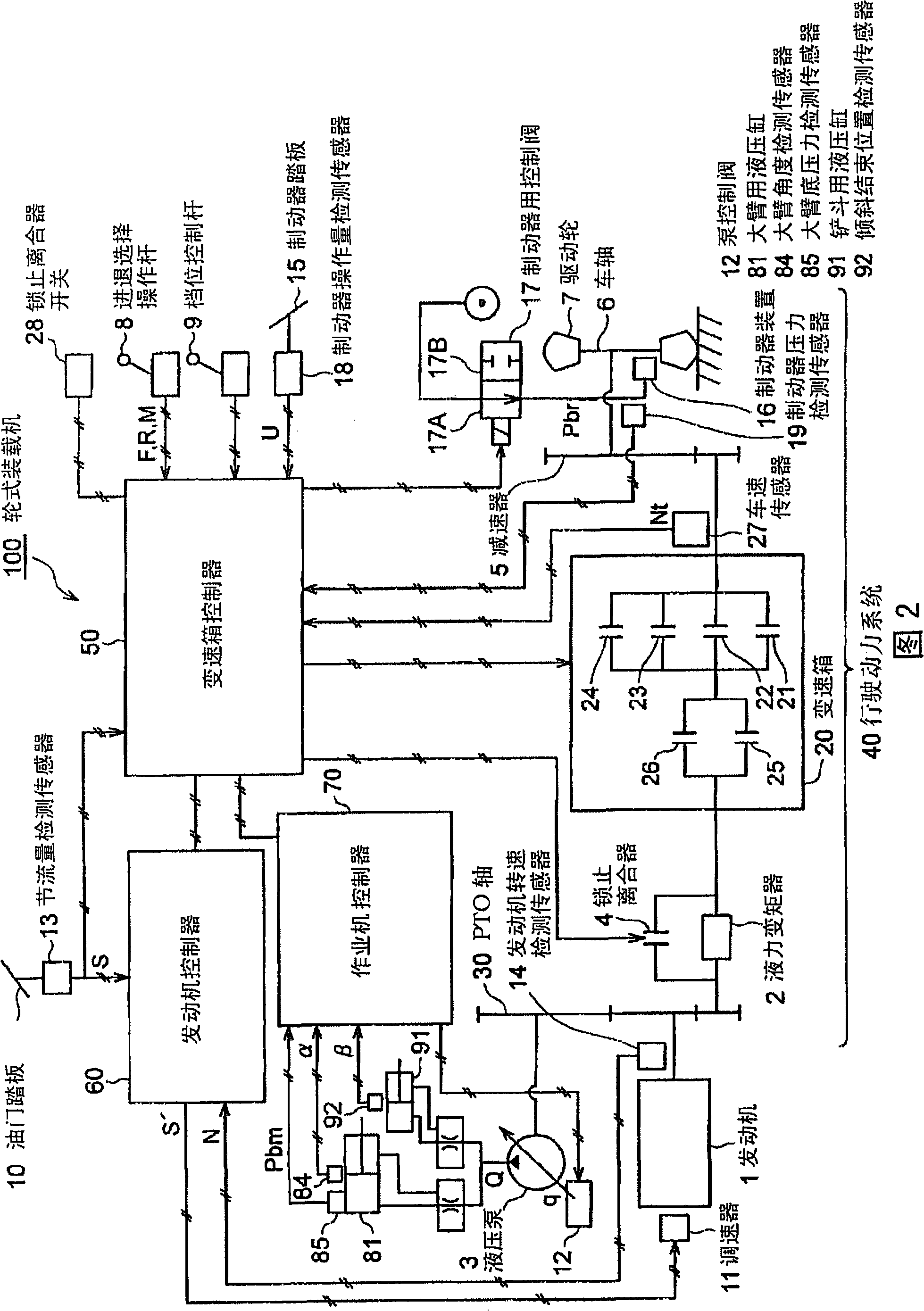
[0038] 2 is a block diagram showing the configuration of a control device for an engine and a hydraulic pump of a work vehicle according to an embodiment, and a part of the present invention shows a configuration of a wheel loader.

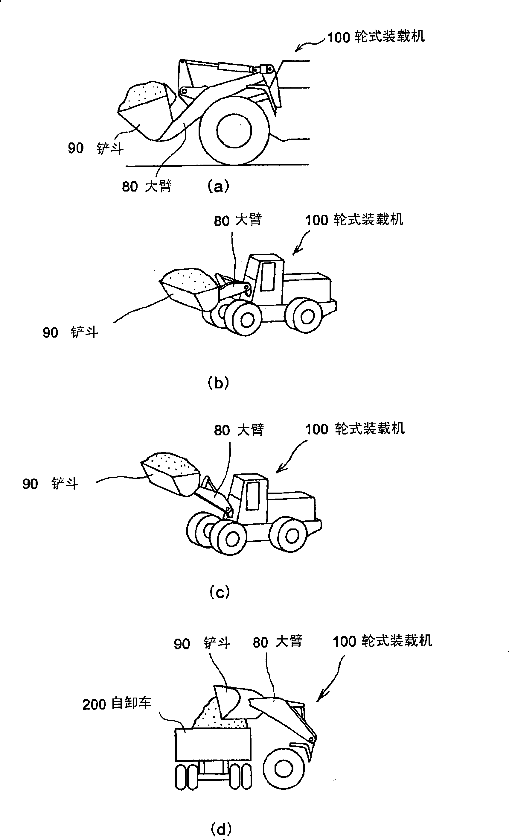
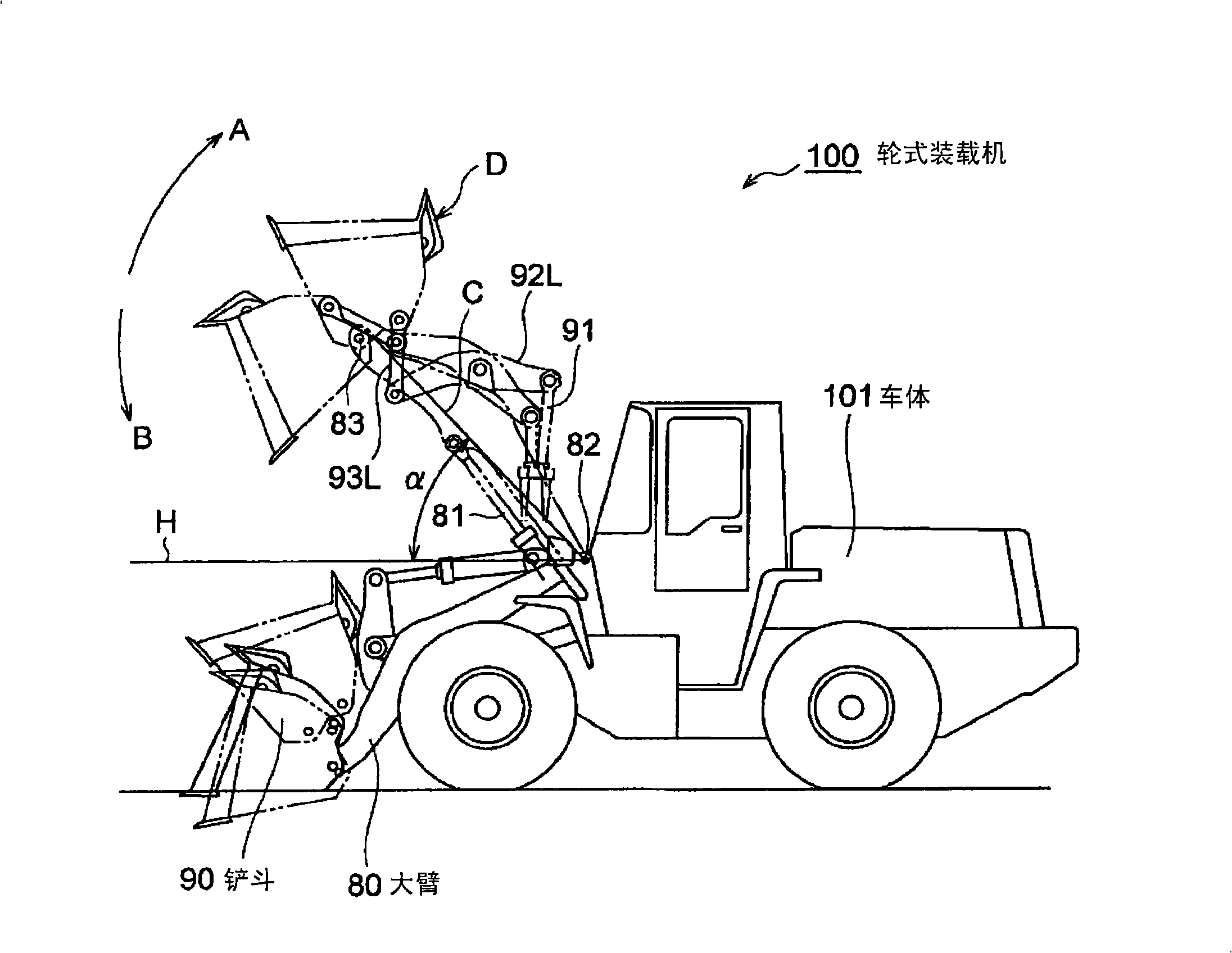
[0039] As shown in FIG. 2 , the wheel loader 100 distributes the power of the engine 1 to the travel power system 40 and the hydraulic pump 3 , and the drive wheels 7 are operated by the travel power system 40 , and the working machine etc. are operated by the hydraulic pump 3 . action.

[0040] The output shaft of the engine 1 of the wheel loader 100 is connected to the PTO shaft 30 . The PTO shaft 30 is connected to the torque converter 2 and also connected to the hydraulic pump 3 . A lock-up clutch 4 for locking the torque converter 2 is arranged in parallel on the torque converter 2 along the power transmission path 40 .

[0041] Par...


PUM


Abstract

An engine of a working truck in which adverse effect of oil temperature rise is avoided, by lessening the load applied to an accelerator when the working truck is traveling while elevating the boom and approaching a place for discharging the load in the bucket during dump approach and, reducing heat generated through operation of a brake, and deterioration in work efficiency of the working truck is avoided by preventing the elevating speed of a boom from decreasing. A hydraulic pump controller and a method for controlling the hydraulic pump are also provided. On condition that a throttle amount sensor detects the operating amount of an acceleration pedal reaching a prescribed threshold value (operation amount 70%), a brake pressure sensor detects operation (brake on) of a brake, and a vehicle speed sensor detects the body speed reaching a prescribed threshold value, a transmission controller delivers a throttle correction command signal for reducing the target engine speed to a governor through an engine controller, and delivers a boom elevating time cam plate inclination angle alteration command for sustaining delivery flow rate of the hydraulic pump by supplementing reduction in delivery flow rate of the hydraulic pump by a throttle correction command to a pump control valve through a working machine controller.

Description

technical field [0001] The present invention relates to a work vehicle which distributes the power of an engine to a traveling power system and a hydraulic pump, operates driving wheels through the traveling power system, and operates a working machine through the hydraulic pump, and particularly relates to a device for controlling the engine and the hydraulic pump and methods. Background technique [0002] The wheel loader distributes the power of the engine to the traveling power system and the hydraulic pump, and the driving wheels are operated by the traveling power system, and the working machine etc. are operated by the hydraulic pump. That is, the output (torque) of the engine is transmitted to the driving wheels through a driving dynamic system (power transmission device) such as a torque converter and a transmission. As a result, the drive wheels are driven, and the wheel loader travels. In this way, part of the horsepower of the engine is consumed as the torque c...

Claims


Application Information

Patent Timeline
IPC IPC(8): E02F9/22F02D29/00F02D29/04
CPCE02F9/2235E02F9/2025F02D29/04E02F9/226E02F9/2296Y10T477/897B60W10/06Y10T477/87B60W30/1888Y10T477/817B60T17/02B60W10/30E02F9/2246
Inventor 畠中靖史
Owner KOMATSU LTD
Why Eureka
Try Eureka