Method and device for applying plane material pieces and embroidery machine

An embroidery machine and embroidery technology, applied in the field of embroidery machines, can solve the problems of high cutting temperature, damage to material layers, etc.

Inactive Publication Date: 2008-10-22
拉泽刺绣机股份公司
View PDF9 Cites 0 Cited by
  • Summary
  • Abstract
  • Description
  • Claims
  • Application Information

AI Technical Summary

Problems solved by technology

A particular disadvantage is also the very high cutting temperatures, which can damage the layers of material underlying the intarsia embroidery material

Method used


Image

  • Method and device for applying plane material pieces and embroidery machine
  • Method and device for applying plane material pieces and embroidery machine
  • Method and device for applying plane material pieces and embroidery machine

Examples


Embodiment Construction

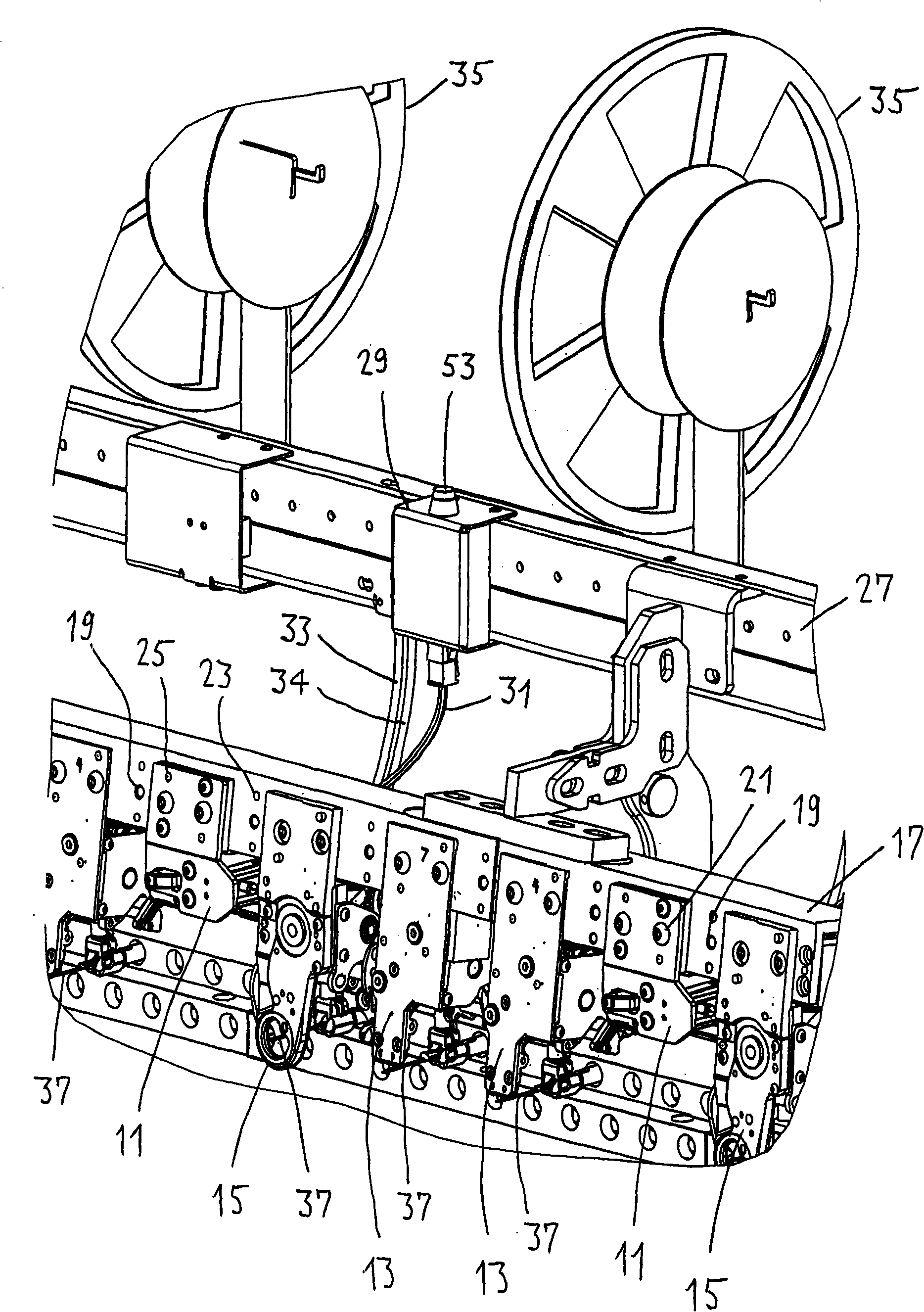
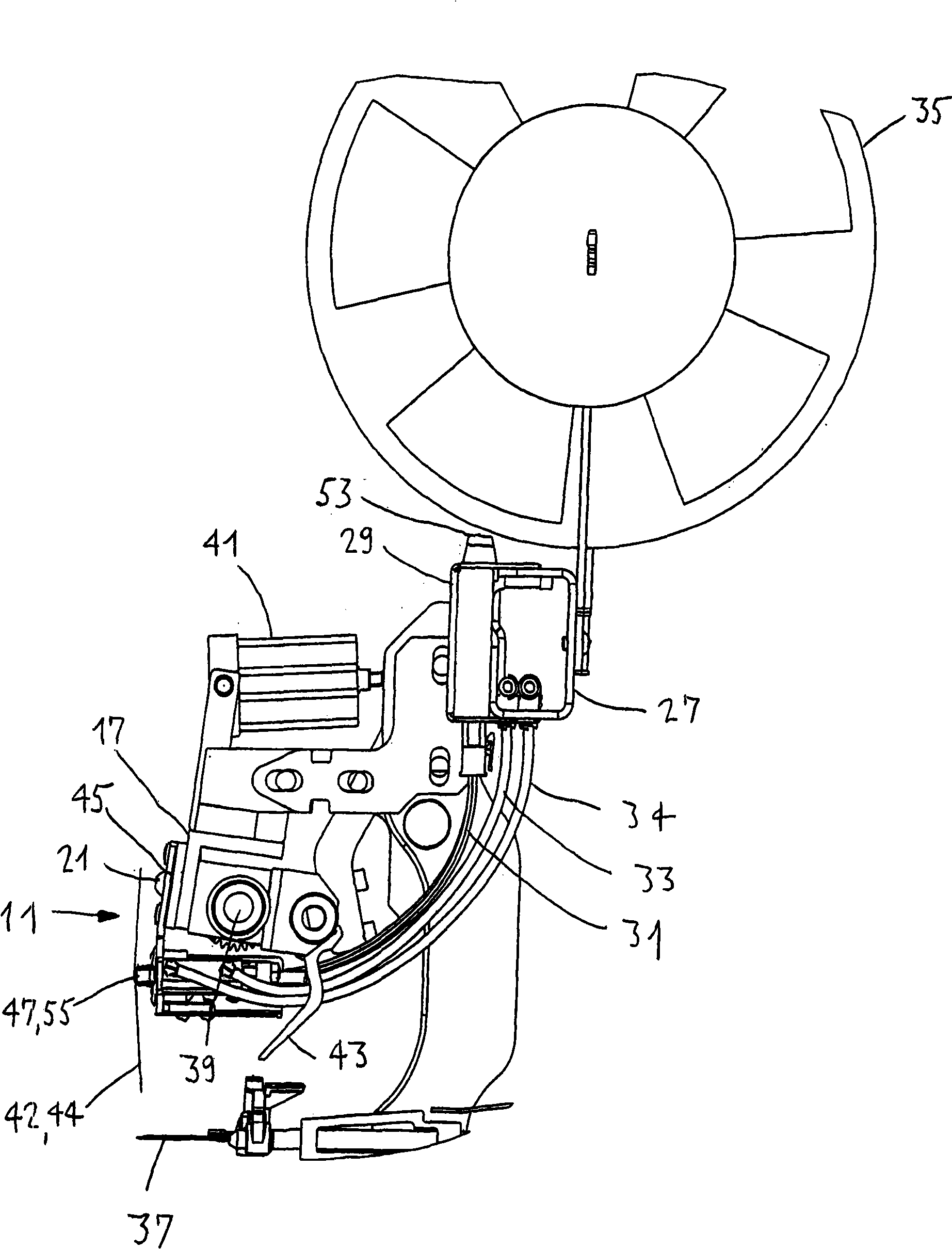
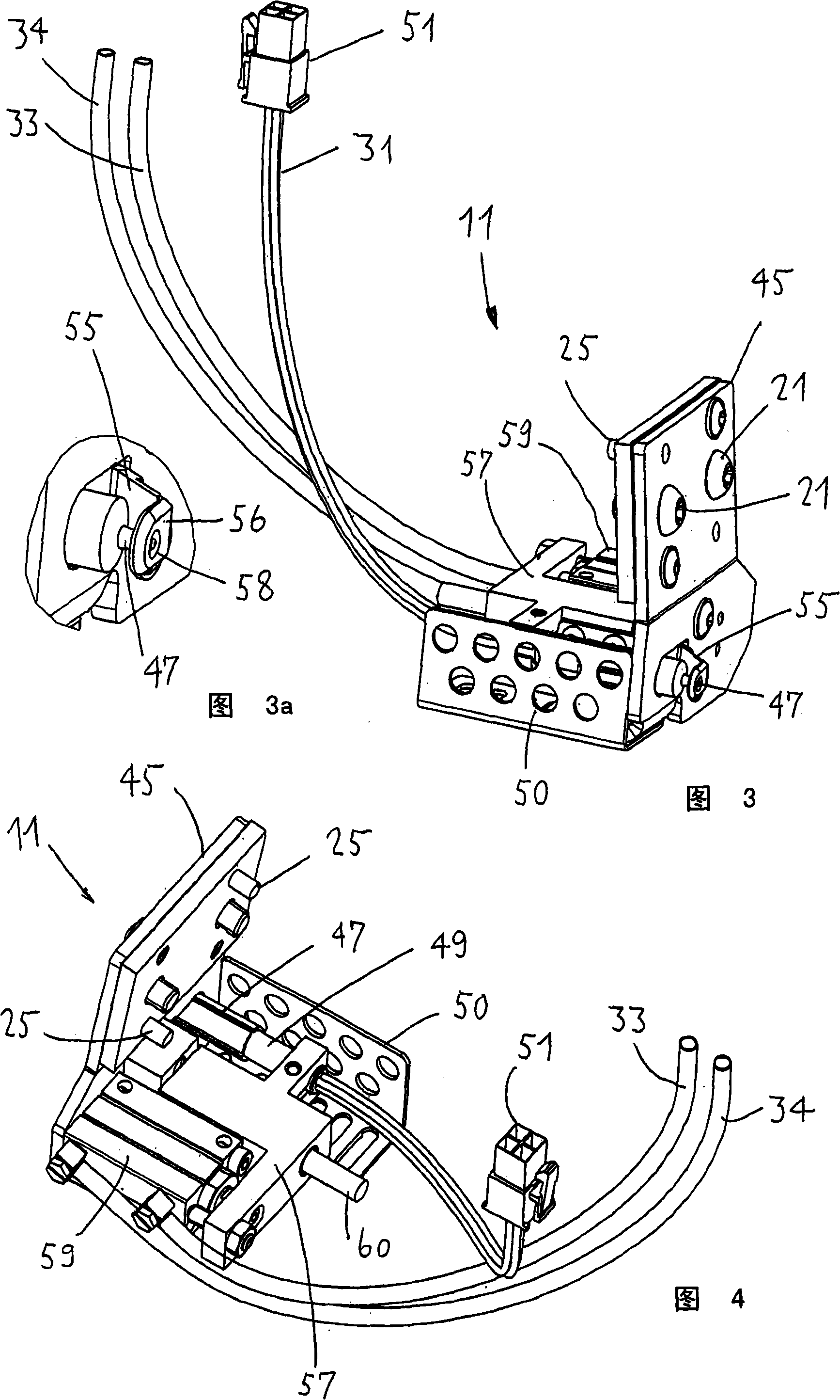
[0032] figure 1Two intarsia embroidery heads 11 are shown together with a patch head 13 and a braided thread head 15 . The trim head 13 is designed like the above-mentioned EP-A-1 764 434, and the braid head 15 is likewise designed like the above-mentioned EP-A-1 764 435. All these intarsia embroidery heads 11, patch heads 13 and braiding heads 15 are fastened easily replaceable on a frame 17 of the rust machine, which frame also has threaded holes 19 for bolts 21 for this purpose and also has holes for The guide hole 23 of the guide pin 25. This enables precise positioning of the intarsia embroidery head 11 , the patch head 13 and the braided thread head 15 . The track 27 also extends the length of the machine. The power supply of the intarsia embroidery head 11 takes place in this track. A power cord 31 and pneumatic hoses 33 , 34 extend from the junction box and fuse box 29 to the intarsia embroidery head 11 . The bobbin for the veneer tape is marked with 35. The embr...


PUM


Abstract

The device (11) is mounted on an embroidery machine in order to process applique embroidery. A bracket (45) is provided with a slider with heated tip (47); the slider moves from the rest position to the indicated cutting position. On the cutting position, an interval keeper (55) is up pressed on a material layer for applique embroidery; the material layer is arranged on the embroidery cloth; wherein, the heated tip as a cutter penetrates into a preferred rayon material layer with a predetermined depth. Through the control of embroidery machine process, the relative movement between the heatedtip (47) and the material layer is realized, thereby cutting the material layer. The cutting is realized by melting the rayon.

Description

technical field [0001] The invention relates to a method and a device for intarsia embroidery of a planar material block having a desired shape to an embroidery base by means of an embroidery machine. The invention also relates to an embroidery machine having at least one such device. Background technique [0002] Embroidery machine here refers to a machine for producing stitches as described in the book "Stickereitechniken" by Schoener / Fricker, Leipzig 1982, p. 18 / 20, which can freely change the direction of each individual stitch within technical limits, usually You can also change the size of the stitches. This can produce decorative patterns. But in recent times, embroidery machines have also used technical functions to produce patterns. Most of the embroidery machines used today work according to the two-thread system, and the embroidery patterns produced on the embroidery base fabric are controlled according to the program. Basically divided into large embroidery m...

Claims


Application Information

Patent Timeline
Patent Type & Authority Applications(China)
IPC IPC(8): D05C7/08D05C13/00D06H7/16
CPCD05C5/04D05C7/10D05B35/06D05C7/08
Inventor F·拉泽
Owner 拉泽刺绣机股份公司
Why Eureka
Try Eureka