A high-efficiency energy-saving anti-icing gate applied to channels

A high-efficiency, energy-saving, gate technology, used in artificial waterways, open-air water surface cleaning, construction, etc., can solve problems such as energy waste and low ice melting efficiency

Active Publication Date: 2021-06-08
NORTH CHINA UNIV OF WATER RESOURCES & ELECTRIC POWER
View PDF9 Cites 0 Cited by
  • Summary
  • Abstract
  • Description
  • Claims
  • Application Information

AI Technical Summary

Problems solved by technology

[0004] The invention aims at the problems that common gates are easy to cause gate accidents and abnormal situations due to icing, and the unreasonable structural design of existing heat-melting anti-icing gates causes energy waste and low melting efficiency. The invention provides a water circulation principle A new type of anti-icing gate based on the principle of heat transfer and heat transfer, in order to achieve the purpose of anti-icing and ensure the normal opening and closing of the gate

Method used


Image

  • A high-efficiency energy-saving anti-icing gate applied to channels
  • A high-efficiency energy-saving anti-icing gate applied to channels
  • A high-efficiency energy-saving anti-icing gate applied to channels

Examples


Embodiment 1

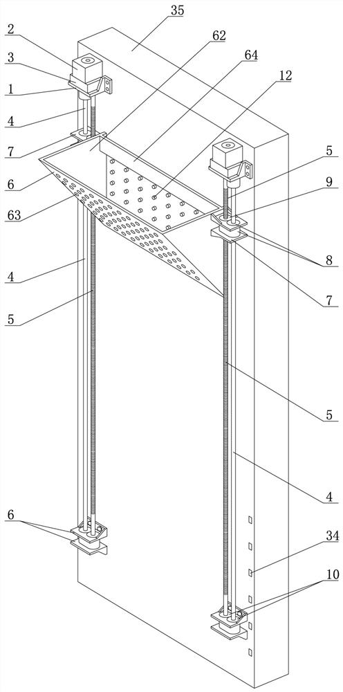
[0023] Embodiment 1: a kind of as figure 1 The anti-icing gate shown in the figure is mainly used in the transformation of the channel gate, which can efficiently and energy-savingly eliminate the ice in front of the gate and protect the safety of the gate.

[0024] From figure 1 It can be seen that a lifting bucket is provided on the side facing the water of the main body 35 of the gate. The tapered lifting bucket 6 in the figure is preferably used, and other shapes such as rectangular or body-shaped lifting bucket structures can also be used. The outer wall of the tapered lifting bucket 6 is an inclined plate 61, the two side walls 62 are vertically connected to the inclined plate 61, the inner sides of the two side walls 62 are fixedly connected by a beam 64, the beam is not in contact with the surface of the gate but there is a matching gap, Thereby, the two side walls 62 of the hoist bucket can be in contact with the ram while the crossbeam is not in contact with the ram...

Embodiment 2

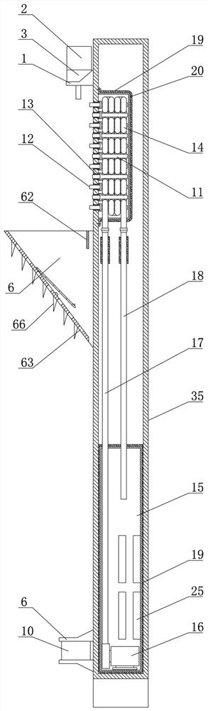
[0033] Embodiment 2: Another anti-icing gate, the content is basically the same as that of Embodiment 1, the difference is the change of the lifting mechanism. The hoisting mechanism that adopts in this implementation is that lifting motor 2 is installed at the top center position of gate, and the rotating shaft of lifting motor 2 is equipped with sheave, and the end of the traction rope wound on the sheave is fixed on the lug of lifting bucket upper center.

Embodiment 3

[0034] Embodiment 3: in the anti-icing gate further improved when embodiment 2 is based on, as Figure 5 As shown, the gravity sensing mechanism adopted is to install a tension sensor between the lifting lug and the traction rope at the upper center of the lifting bucket.


PUM


Abstract

The invention discloses a high-efficiency energy-saving anti-icing gate applied to a channel. A lifting bucket is arranged on the side facing the water of the gate, a lifting mechanism for driving the lifting bucket is arranged on the top of the gate, and a heating zone is arranged on the upper part of the gate. The bottom of the gate is equipped with a temperature sensor for monitoring the temperature of the water body. The temperature sensor provides a start signal to the controller to make the controller control the lifting mechanism and the heating mechanism to work. A gravity sensing mechanism is set in the lifting bucket, and the gravity sensing mechanism provides the controller with a stop signal. Or the return signal makes the lifting mechanism and the heating mechanism stop or cycle. The present invention adopts the structure of the anti-icing gate and the automatic control system based on the principle of crushing, lifting and separating the frozen ice layer, which can at least The ice body in a certain width range in front of the gate is broken and melted, preventing the ice body from causing additional load on the gate and affecting the safety of the gate.

Description

technical field [0001] The invention belongs to the technical field of gate anti-icing, and in particular relates to a high-efficiency, energy-saving ice-breaking and deicing gate applied to channels. Background technique [0002] In water conservancy projects, single or multiple gates are generally arranged side by side, and act simultaneously or separately, so as to realize the control of water flow. However, in the low temperature environment of the low temperature area, the upper part of the gate will freeze, which greatly increases the load of the gate and seriously affects the up and down movement or opening and closing of the gate, especially for reservoirs, rivers and lakes located in high latitude or high altitude severe cold areas , the freezing period is long, and the maximum thickness of the ice layer is more than 1.5m. If the ice is not removed in time and anti-freezing measures are not taken, the gate will freeze, which will lead to the deformation of the water...

Claims


Application Information

Patent Timeline
Patent Type & Authority Patents(China)
IPC IPC(8): E02B5/08E02B15/02
CPCE02B5/082E02B15/02
Inventor 许新勇齐静许文杰
Owner NORTH CHINA UNIV OF WATER RESOURCES & ELECTRIC POWER
Why Eureka
Try Eureka