
Compact type core construction

A compact, iron-core technology, applied in the field of iron-core structure, can solve the problems of increased production cost, small DC excitation ampere-turn, difficult insulation, etc., and achieves the effect of strengthening excitation degree, reasonable iron core structure, and reducing manufacturing cost.

Inactive Publication Date: 2008-10-22
北京云电英纳超导电力技术有限公司 +1
View PDF0 Cites 10 Cited by
  • Summary
  • Abstract
  • Description
  • Claims
  • Application Information

AI Technical Summary

Problems solved by technology

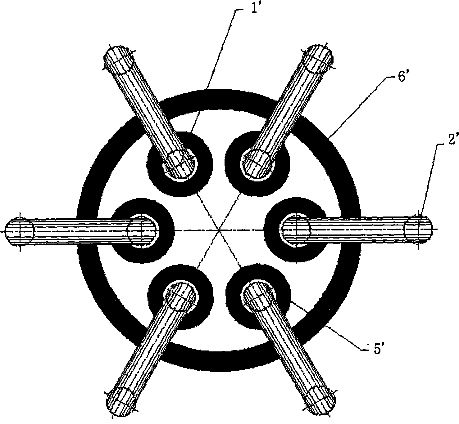
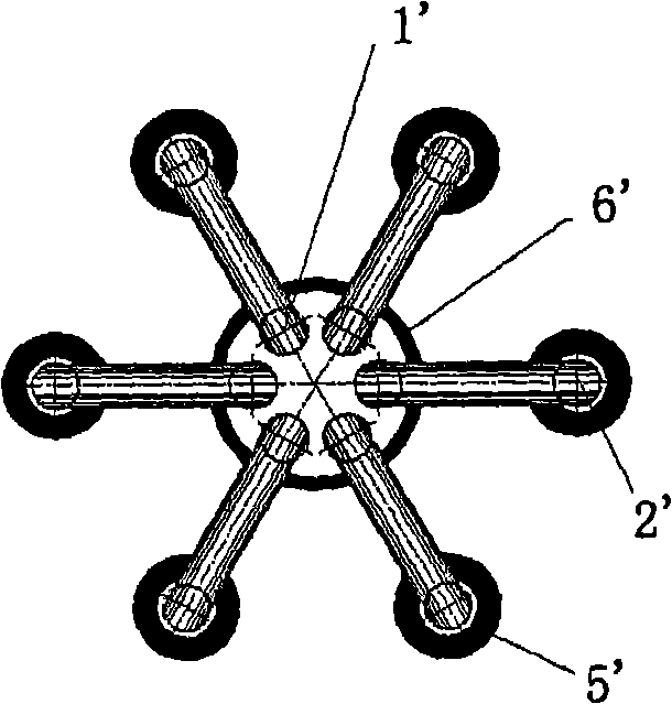
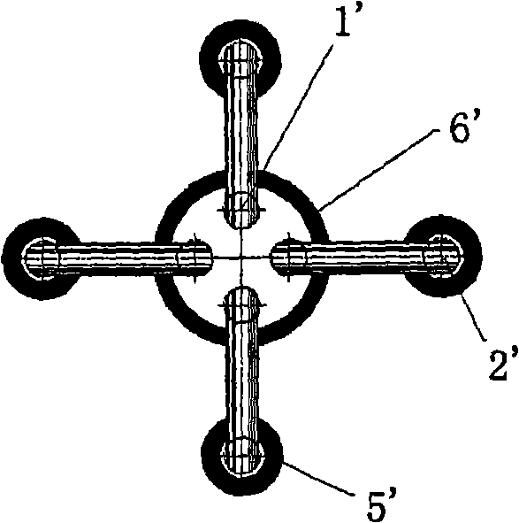
Tightly coupled structures such as figure 1 Shown, AC winding 5' and DC winding 6' same Located on the combined center column, its coupling coefficient is relatively high, and the DC excitation ampere-turn required to make the AC core reach the deep saturation state required by the work is relatively small, but for high voltage levels, the high voltage winding inside and the low voltage winding outside The structure makes insulation difficult, making and maintaining difficult. In addition, the diameter of the control DC winding 6' increases, thereby increasing the amount of DC winding material. For a superconducting current limiter, the DC winding 6' is a superconducting tape material, the price is relatively expensive, so the production cost is increased; while the traditional loosely coupled structure such as Figure 2-1 , 2-2 , 2-3, and 2-4, the DC winding 6' and the AC winding 5' are located on different core columns (middle core column 1' and side column 2') of the same core window, that is, they are respectively located on the middle core column 1' and the side column 2', at the same time, there is a large gap between the DC winding 6' and the middle iron core column 1' and the center of the iron core column where each intermediate iron core column 1' is assembled together, and the space utilization rate is low; at the same time, the DC winding 6 The degree of coupling between ' and the AC winding 5' is also greatly reduced, so that the magnetic flux leakage on the middle core column 1' increases

Method used


Image

  • Compact type core construction
  • Compact type core construction
  • Compact type core construction

Examples


Embodiment Construction

[0039] Embodiments and specific implementation methods of the present invention will be described in detail below in conjunction with the accompanying drawings.

[0040] Such as Figure 3-1 to Figure 3-4 As shown, it is a schematic diagram of the compact iron core structure of the present invention. The compact iron core structure includes 2 to 6 square-shaped iron cores, Figure 3-1 It is a six-core structure, Figure 3-2 It is a four-core structure, Figure 3-3 It is a three-core structure, Figure 3-4 It is a two-core structure, and each square-shaped core includes a middle core column 1, a side column 2, and upper and lower yokes 3, 4, and each side column 2 is equipped with an AC winding 5, wherein the middle core column 1 The cross-sectional shape of the side column 2 is different from the cross-sectional shape of the side column 2. 2 to 6 of the intermediate core columns are compactly combined and assembled into a combined center column around the center for 360°, an...


PUM

PropertyMeasurementUnit
Angleaaaaaaaaaa

Abstract

The invention relates to a compact iron core structure, which comprises two to six mouth-shaped iron cores, wherein, each mouth-shaped iron core comprises an intermediate iron core column, a side column, an upper yoke iron and a lower yoke iron. Each side column is sleeved with an alternating current winding, the cross-section shape of the intermediate iron core column is different from that of the side column, two to six of the intermediate iron core columns are compactly combined and assembled into a combined intermediate column which has an angle of 360 DEG around the center, an assembled insulating partition is arranged between each two intermediate iron core columns, the outline of a cross-section rim of the combined intermediate column is of a circle, and one direct current winding is sleeved outside the combined intermediate column. The iron core structure effectively utilizes space to ensure that the iron core structure is more reasonable, reduces the whole volume of a saturable core superconducting fault current limiter and a saturable reactor and so on, strengthens the excitation degree of the direct current winding to the iron cores, decreases the magnetic leakage, reduces manufacturing cost, and contributes to industrialized application.

Description

technical field [0001] The invention relates to an iron core structure, especially a compact iron core structure, which is suitable for equipment with a DC control system, especially electromagnetic equipment such as a saturated iron core type superconducting fault current limiter and a saturated reactor. Background technique [0002] In some devices using the principle of saturable reactors, such as saturated iron core type superconducting fault current limiters, etc., the core components for function realization are the iron core, DC winding and AC winding, and the most important structural design is to consider the layout of the iron core and windings Coordination, winding layout affects its volume, electromagnetic characteristics, and also has a great impact on economy and manufacturing process. [0003] There are two coupling forms for AC winding and DC winding. Tightly coupled structures such as figure 1 Shown, AC winding 5' and DC winding 6' same Located on the co...

Claims


Application Information

Patent Timeline
IPC IPC(8): H01F3/00H01F27/24H01F41/02
CPCY02E40/69
Inventor 牛潇晔张敬因高越农王洋田波龚伟志信赢崔健李正华
Owner 北京云电英纳超导电力技术有限公司
Learn More