Reaction jet welding device and uses thereof

A technology of welding device and jet flow, which is applied in the directions of tin feeding device, auxiliary device, welding equipment, etc., can solve the problem that the application range cannot be expanded.

Inactive Publication Date: 2008-10-29
杨国金
View PDF1 Cites 17 Cited by
  • Summary
  • Abstract
  • Description
  • Claims
  • Application Information

AI Technical Summary

Problems solved by technology

The scope of application of the above-mentioned invention titled "Soldering apparatus" (Soldering apparatus) cannot be extended to the welding field of electronic wire products other than the field of PCB (printed electronic circuit board) welding. ...

Method used


Image

  • Reaction jet welding device and uses thereof
  • Reaction jet welding device and uses thereof
  • Reaction jet welding device and uses thereof

Examples


Embodiment Construction

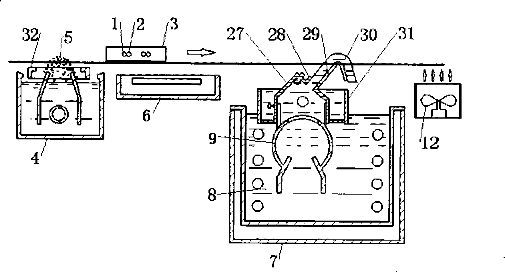
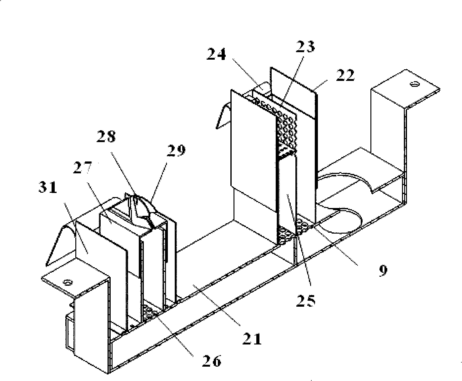
[0024]The jet welding device of the present invention is an improved welding device, including a fixture 3, a flux generator 4, a preheater 6, a flux tank 8 with a primary nozzle, a voltage stabilizing filter 21, and a nozzle 27; The preheater 6 is installed on the downstream of the flux generator 4 that applies the flux to the spot to be soldered; the flux tank 8 with a primary nozzle is located downstream of the above preheater; the voltage stabilizing filter 21 is located on the primary nozzle 9, There is an overflow cover 22 and a secondary spout 26 installed with an adjustable-height overflow baffle 23 in the middle; the nozzle 27 is installed above the above-mentioned secondary spout 26, and consists of a spout 28 with a millimeter size and a pair of spouts along the The deflectors 29 arranged symmetrically in the "eight" shape extended by the parabolic trajectory of the flux flow are combined to form a flux jet flow (ie, a millimeter-scale welding pool) 30 with the upper...


PUM


Abstract

The invention discloses an injection stream welding plant and the application thereof. The injection stream welding plant comprises a clamp, a soldering flux generator, a preheater, a solder groove with a first-level spout, a voltage-stabilizing filter and a nozzle; the preheater is arranged downstream the soldering flux generator; the solder groove is located downstream the soldering flux generator; the voltage-stabilizing filter is positioned behind the solder groove and has an overflow cover and a second-level spout, wherein, an overflow baffle with adjustable height is arranged in the middle of the overflow cover; the nozzle is arranged on above the second-level spout and provided with a millimeter-level sized spout and a pair of nozzles which extend along the parabola trace of the solder stream, are arranged symmetrically in the shape of an inverted V and combined by blast baffles and form a millimeter-level section sized solder injection stream that hangs in the air to be exposed in the upper, left and right sides. The application of the injection stream welding plant of the invention is that the application of the wave-soldering welding technology is extended to the electronic product welding field of none-plane-type welding point arrangement between electronic wires and electronic elements beyond the plane-welding PCB welding field. The injection stream welding plant has the advantages of being capable of realizing consecutive welding and being used in the welding between none-plane electronic wires and electronic elements.

Description

technical field [0001] The present invention relates to a welding device and its application, in particular to a jet flow welding device for products with non-planar solder point arrangement and its application. Background technique [0002] Tin soldering of electronic connectors in the electronics industry usually uses soldering iron soldering, wave soldering, reflow soldering, etc. For example, soldering iron is used for plug and wire, wave soldering is used for PCB pin components, and reflow soldering is used for PCB chip components. In terms of soldering efficiency and soldering quality, wave soldering and reflow soldering are at the same level, while soldering iron soldering is not as good as the former two. At present, wave soldering is only suitable for soldering PCB components, that is, tin soldering with solder joints distributed on a flat plate, and cannot be used for soldering products with non-planar solder joints. Therefore, under the current conditions, the s...

Claims


Application Information

Patent Timeline
IPC IPC(8): B23K3/00B23K3/06B23K3/08B23K1/08H01R43/02
Inventor 杨国金
Owner 杨国金
Why Eureka
Try Eureka