

Biomass fuel thermal decomposition vaporization combustion method and apparatus
A technology of biomass fuel and combustion method, which is applied in the direction of combustion method, combustion type, combustion equipment, etc., can solve the problems of irreplaceable, large investment, complex system, etc., and achieve the effect of reducing dust effect, small resistance, and wide application range
Inactive Publication Date: 2008-10-29
韩枫
View PDF0 Cites 26 Cited by
- Summary
- Abstract
- Description
- Claims
- Application Information
AI Technical Summary
Problems solved by technology
However, the various methods currently produced have problems such as complex systems, large investment, and poor efficiency, and cannot replace the commonly used coal-fired boilers.
Method used
View moreImage
Smart ImageViewing Examples

Examples
Embodiment Construction
Login to View More PUM
 Abstract
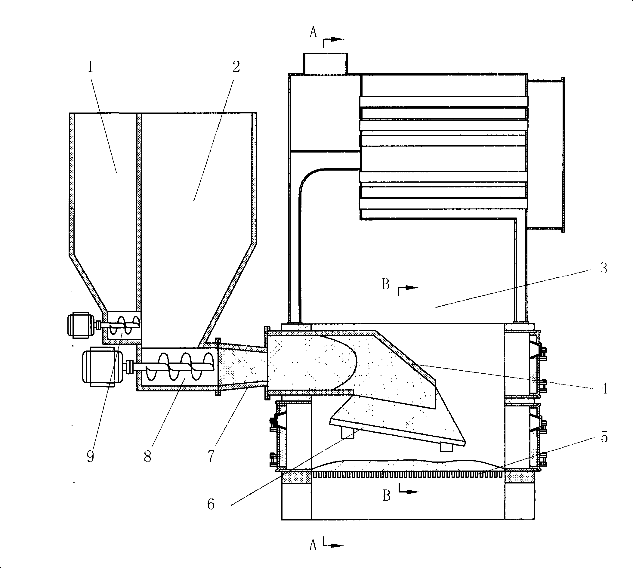
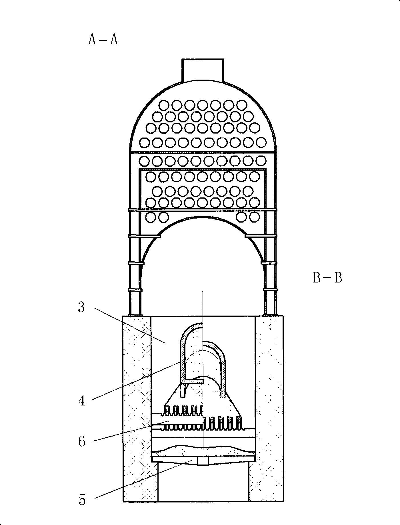
A gasification and combustion device for biomass fuel pyrogenation is provided with the technical proposal as follows: a pyrogenation device is added in the hearth of a boiler and is composed of a pyrogenation cylinder and a pyrogenation furnace, and a material feeding device is arranged out of the hearth. The biomass fuel is pushed forward by a main spiral propeller and is gradually compressed when passing through a fuel passage to improve the degree of compaction and prevent pyrogenation gas from escaping, the biomass fuel is pushed to move on by the subsequent fuel after entering the pyrogenation cylinder, and gradually falls on the pyrogenation furnace bed to come into contact with oxygen for being ignited, the pyrogenation cylinder is heated by flame after ignition, the biomass fuel in the pyrogenation cylinder is heated to a temperature being higher than that of pyrogenation, the biomass fuel carries out gas-solid separation, the gas can only escape from the flame on the pyrogenation furnace bed, and the combustible component therein is subjected to forced ignition, the flame goes up to the upper part of the hearth along the latearal face of the pyrogenation cylinder and is burnt out, at the same time the pyrogenation cylinder is heated for the continuous pyrogenation reaction therein, and the solid on the pyrogenation furnace bed is broken to pieces, and falls or continuously burns on the pyrogenation furnace bed.
Description
Biomass fuel pyrolysis vaporization combustion method and device technical field The invention relates to a biomass fuel pyrolysis vaporization combustion technology, in particular to a biomass fuel pyrolysis vaporization combustion method and device. Background technique Due to the increasing shortage of coal resources, countries all over the world are researching biomass combustion utilization technology to solve the problems caused by the energy crisis. At present, the biomass-fired boilers that have been launched are all developed on the basis of coal-fired boiler technology. However, due to the high water content, low volatile point, high volatile content and low energy density of biomass fuel, it is difficult to form stable combustion conditions with coal-fired boiler technology. Therefore, the feasible method is to vaporize or carbonize the biomass to increase the energy density, and then send it to the boiler for combustion. However, the various methods produced a...
Claims
Login to View More Application Information
Patent Timeline
 Patent Type & AuthorityApplications(China)
IPC IPC(8): F23G5/027F23K3/14
Inventor韩枫
Owner韩枫