Switched mode power supply with synchronous rectifier

A technology of synchronous rectification switch and switch, which is applied in the direction of instruments, electrical components, and adjustment of electrical variables, etc., can solve problems such as error detection, and achieve the effect of high efficiency, high efficiency, and long blanking time

Active Publication Date: 2008-10-29
NXP BV
View PDF0 Cites 6 Cited by
  • Summary
  • Abstract
  • Description
  • Claims
  • Application Information

AI Technical Summary

Problems solved by technology

This voltage reflected to the secondary side determines the noise in the INHIBIT pin which will cause false detection of discontinuous mode

Method used


Image

  • Switched mode power supply with synchronous rectifier
  • Switched mode power supply with synchronous rectifier
  • Switched mode power supply with synchronous rectifier

Examples


Embodiment Construction

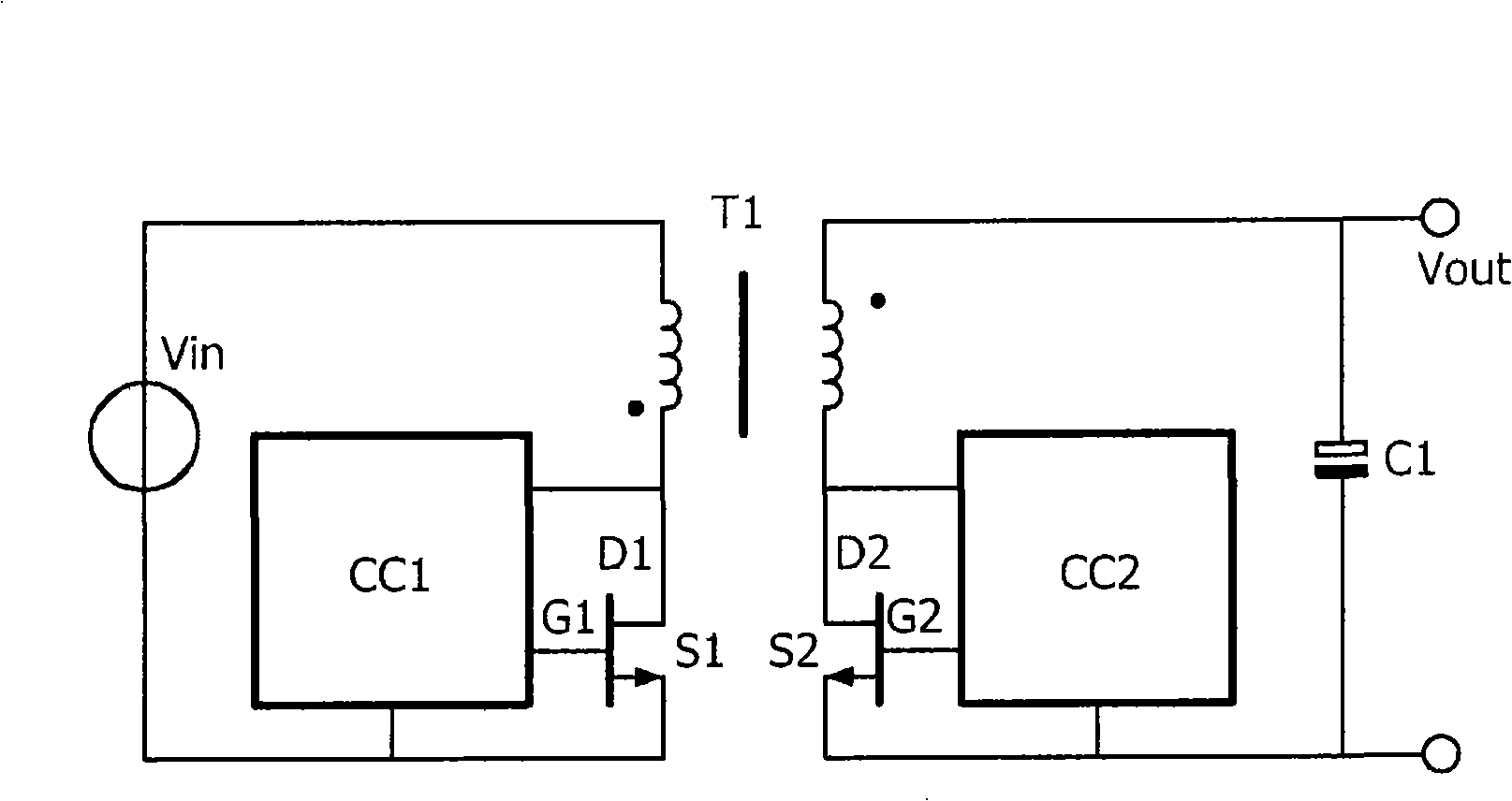
[0013] figure 1 An embodiment of a switched mode power supply with synchronous rectifiers is shown. The series connection of the primary winding of the transformer T1 and the primary switch S1 is connected between the two terminals of the voltage source Vin. The primary controller IC CC1 receives the drain voltage D1 of the primary switch S1 and controls the gate voltage G1 of the primary switch S1. The series connection of the secondary winding of the transformer T1 and the secondary switch S2 is connected between both ends of the output capacitor C1, and the output voltage Vout can be obtained from the output capacitor C1. The secondary controller IC CC2 receives the drain voltage D2 of the secondary switch S2, and controls the gate voltage G2 of the secondary switch S2.

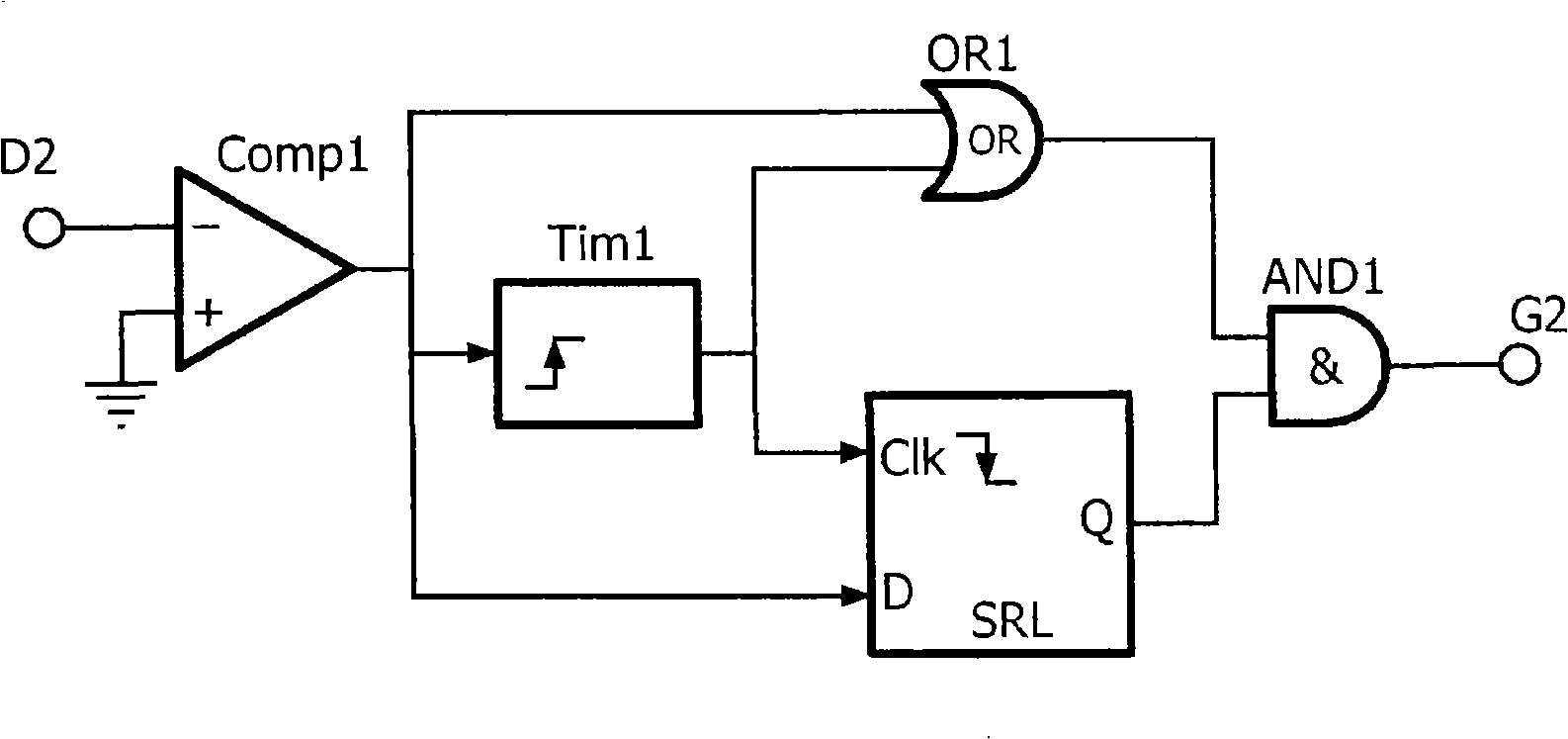
[0014] figure 2 shows the use of the figure 1 The secondary controller CC2 in the circuit. The comparator Comp1 outputs a voltage indicative of the positive or negative drain voltage D2. Once the dr...


PUM


Abstract

In a controller (CC2) for controlling a synchronous rectification switch (S2), the controller (CC2) comprises a sensing circuit (SRL) for sensing an output (D2) of the synchronous rectification switch (S2) at an end of a blanking time to obtain a sense signal (Q), and a control signal generating circuit (ANDl) for generating a control signal (G2) for the synchronous rectification switch (S2) in dependence on the sense signal (Q).

Description

technical field [0001] The invention relates to a switched-mode power supply with a synchronous rectifier. Background technique [0002] ST Microelectronics application note AN1804 describes the functionality and operation of the STSR30 device as a secondary synchronous rectifier driver in a flyback topology switch-mode power supply. The IC generates a drive signal with a set dead time relative to the primary side PWM signal from a synchronous clock input taken on the secondary side of the isolation transformer. When the primary switch is turned off, there is usually spikes and ringing at its drain. This voltage reflected to the secondary side determines the noise in the INHIBIT pin that causes false detection of the discontinuous pattern. To avoid this phenomenon, there is a blanking time in the INHIBIT comparator. Once the falling threshold of the clock is detected, the INHIBIT comparator is disabled for 700 ns to avoid any false triggering due to switching noise. This...

Claims


Application Information

Patent Timeline
Patent Type & Authority Applications(China)
IPC IPC(8): H02M3/335
CPCY02B70/1475H02M3/33592Y02B70/10
Inventor 琼·维夏德·斯特里耶克
Owner NXP BV
Why Eureka
Try Eureka