Changeable built-in live center

A live top and replaceable technology, which is applied in the direction of grinding machines, metal processing equipment, grinding/polishing equipment, etc., can solve the problems that the rotation accuracy cannot meet the processing accuracy, the bracket is worn, and the processing benchmark is lost, so as to improve the enterprise market. Competitiveness, ease of replacement and maintenance, and improved accuracy and rigidity

Active Publication Date: 2010-06-09
河南活顶尖机械有限公司
View PDF4 Cites 0 Cited by
  • Summary
  • Abstract
  • Description
  • Claims
  • Application Information

AI Technical Summary

Problems solved by technology

[0002] At present, most of the centers used on heavy machine tools such as roll machinery in the market are dead centers. During the grinding process, the two center holes of the workpiece are easily damaged, the bracket is worn, the processing standard is lost, and the processing accuracy cannot be guaranteed. The existing The live center is mostly used in small equipment due to limited load-bearing and difficult support. The live center usually adopts rolling bearings. The clearance of the rolling bearing makes the rotation accuracy of the live center itself unable to meet the processing accuracy requirements. In addition, its parts are easy to wear and tear. Short life and low cutting efficiency lead to high production costs, which cannot meet the needs of enterprise production and restrict the development of enterprises
In the prior art, the shaft arm at the tip is relatively long, and generally the shaft arm is set at the outer end of the equipment, which increases the force on the shaft arm and cannot withstand the use of large-tonnage equipment; the top head cannot be replaced, and its bearing capacity Small, when the bearing capacity is greater than 50 tons, the damage rate of the tip increases, which cannot meet the normal production needs

Method used


Image

  • Changeable built-in live center
  • Changeable built-in live center
  • Changeable built-in live center

Examples


Embodiment Construction

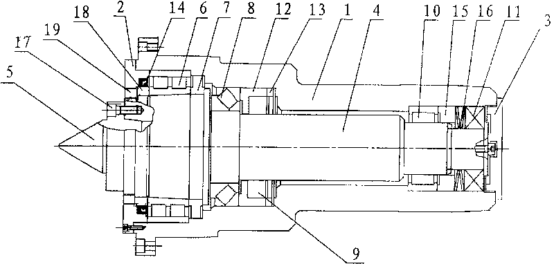
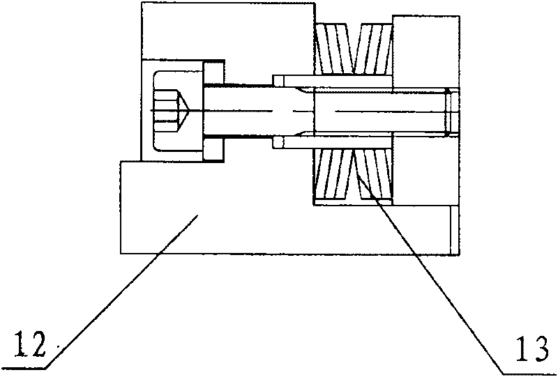
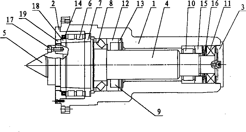
[0021] Such as figure 1 The replaceable built-in live center shown includes seat shell 1, front end cover 2, rear end cover 3, top shaft 4 installed in seat shell 1 and center head 5 arranged on top shaft 4, the front end of top shaft 4 is connected with Double-row short cylindrical roller bearings 6 are installed between seat shells 1, needle roller bearings 10 and deep groove sealed bearings 11 are arranged at the rear end of the top shaft 4, and adjustment pads 7 are arranged on one side of double-row short cylindrical roller bearings 6 , the top head 5 is a replaceable movable component, fixed on the top shaft 4 by the fastening screw 17, a thrust self-aligning roller is arranged between the step surface in the middle of the top shaft 4 and the matching step surface inside the seat shell 1 Bearing 8, the thrust self-aligning roller bearing 8 is pressed by the disc spring 16 arranged at the rear end of the top shaft 4, and the top shaft 4 is pulled back and always pressed o...


PUM


Abstract

The invention provides a replaceable built-in movable tip, comprising a base shell, a front end cover, a rear end cover, a tip shaft arranged in the base shell and a tip head arranged on the tip shaft, wherein, a cylindrical ball bearing is arranged between the front end of the tip shaft and the base shell; the rear end of the tip shaft is provided with a needle roller bearing and a deep groove sealing bearing; one side of the cylindrical ball bearing is provided with an adjusting cushion; a pushing force centering ball bearing is arranged between the step surface of the middle part of the tipshaft and the step surface matched with the internal side of the base shell; the rear end surface of the pushing force centering ball bearing is uniformly provided with at least three groups of elastic components; the tip head is a replaceable and movable component and fixed on the tip shaft by tightening screws. The replaceable built-in movable tip has an extension end with short cantilever, good rigidity, long service life, large bearing weight, high precision, good processing technology and replaceable tip head, facilitates the replacement and maintenance, saves the middle bracket, greatlyreduces the production cost, and improves the market competitiveness of the enterprises.

Description

technical field [0001] The invention relates to heavy-duty roll machinery and equipment, in particular to a replaceable built-in live top used for heavy-duty roll machinery and equipment. technical background [0002] At present, most of the centers used on heavy machine tools such as roll machinery in the market are dead centers. During the grinding process, the two center holes of the workpiece are easily damaged, the bracket is worn, the processing standard is lost, and the processing accuracy cannot be guaranteed. The existing The live center is mostly used in small equipment due to limited load-bearing and difficult support. The live center usually adopts rolling bearings. The clearance of the rolling bearing makes the rotation accuracy of the live center itself unable to meet the processing accuracy requirements. In addition, its parts are easy to wear and tear. Short life and low cutting efficiency lead to high production costs, which cannot meet the needs of enterpri...

Claims


Application Information

Patent Timeline
Patent Type & Authority Patents(China)
IPC IPC(8): B24B5/37B24B5/02
Inventor 张朝煌高化民
Owner 河南活顶尖机械有限公司
Why Eureka
Try Eureka