Buried type garbage compressor

A garbage compressor, buried technology, applied in the direction of presses, manufacturing tools, etc., can solve the problems of wear and tear of the lifting connection part of the collision box, increase the floor height of the transfer station building, and increase the time of one cycle of the equipment, and achieve daily life. Easy to maintain, convenient for daily maintenance, simple structure

Inactive Publication Date: 2008-11-05
阮志华
View PDF2 Cites 9 Cited by
  • Summary
  • Abstract
  • Description
  • Claims
  • Application Information

AI Technical Summary

Problems solved by technology

To sum up, although the above equipment has a good garbage disposal effect, there are disadvantages: first, the high equipment installation space will inevitably increase the floor height of the transfer station building, and the cost of infrastructure construction will be high; second, the separation structure of the compression device and the garbage bin, High manufacturing cost and cumbersome structure; third, the workload of on-site installation of the equipment is large, the construction period is long, and the operability is not strong; fourth, the long-stroke operation of the press table increases the cycle time of the equipment, At the same time, the use efficiency of the equipment is reduced; fifth, the lifting of the box body is carried out by pressing the table, and the up and down operation of the garbage box is easy to be unstable, and it is difficult to load the garbage, which is likely to cause collisions between the garbage box and the vehicle and accelerate the lifting of the box body. Wear and tear, which in turn will reduce the service life of the equipment

Method used


Image

  • Buried type garbage compressor
  • Buried type garbage compressor
  • Buried type garbage compressor

Examples


Embodiment Construction

[0031] The present invention will be further described in detail below in conjunction with the accompanying drawings and embodiments.

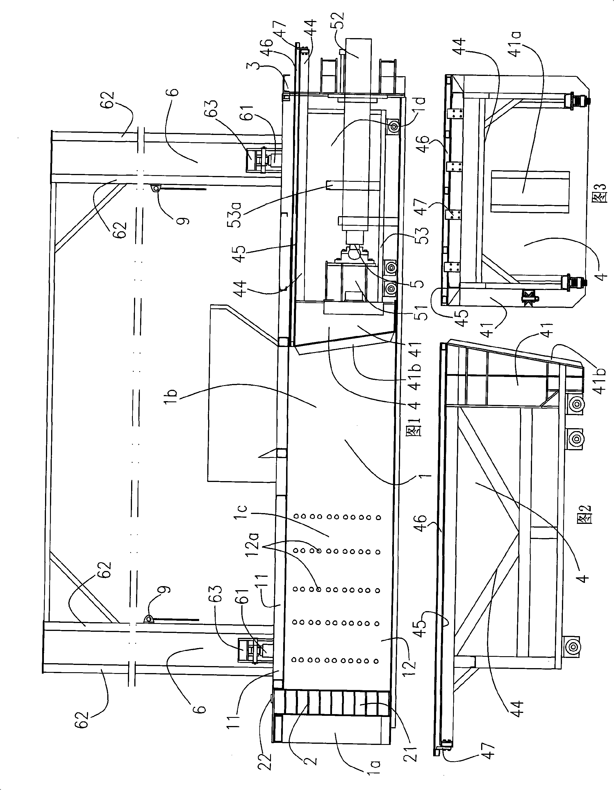
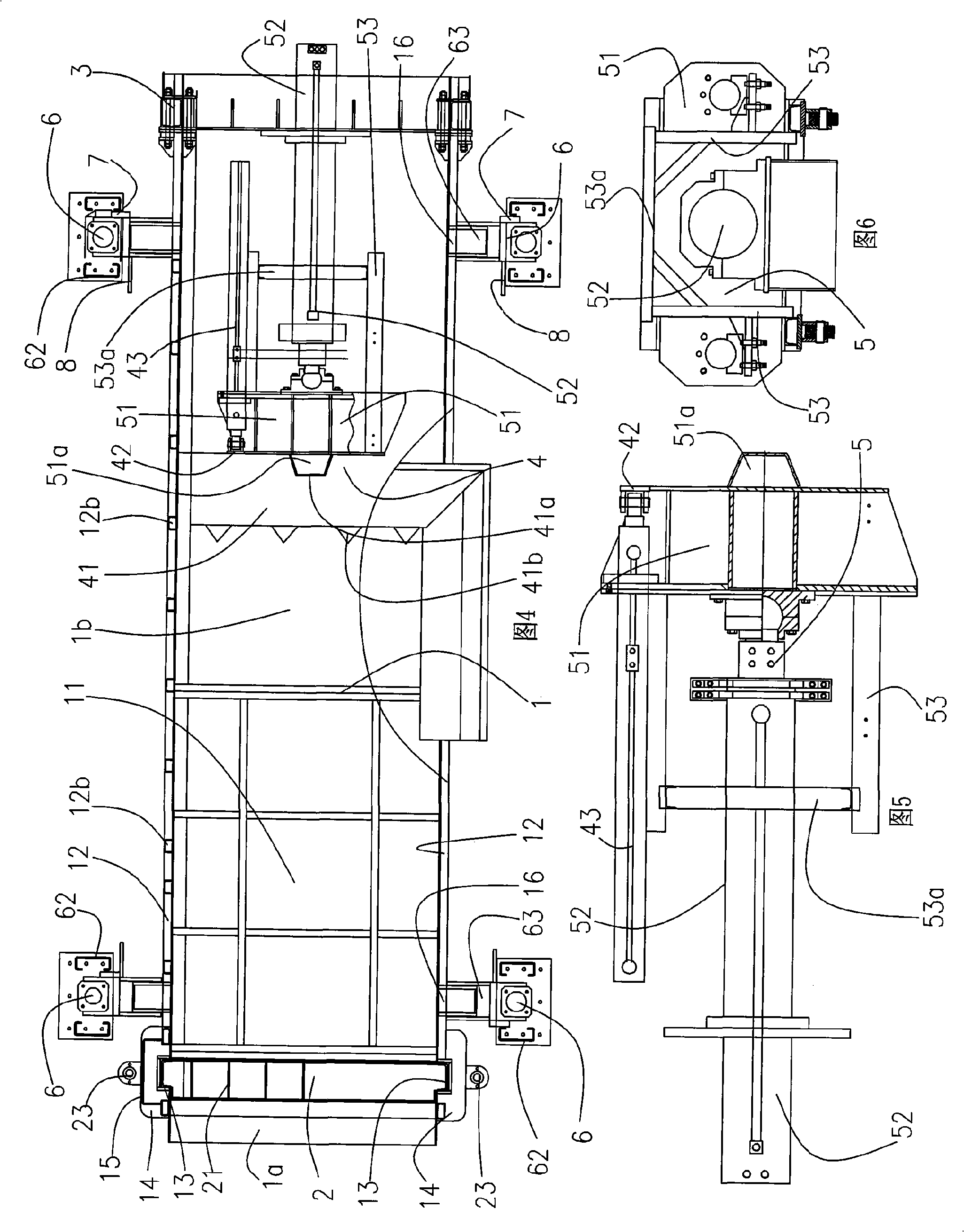
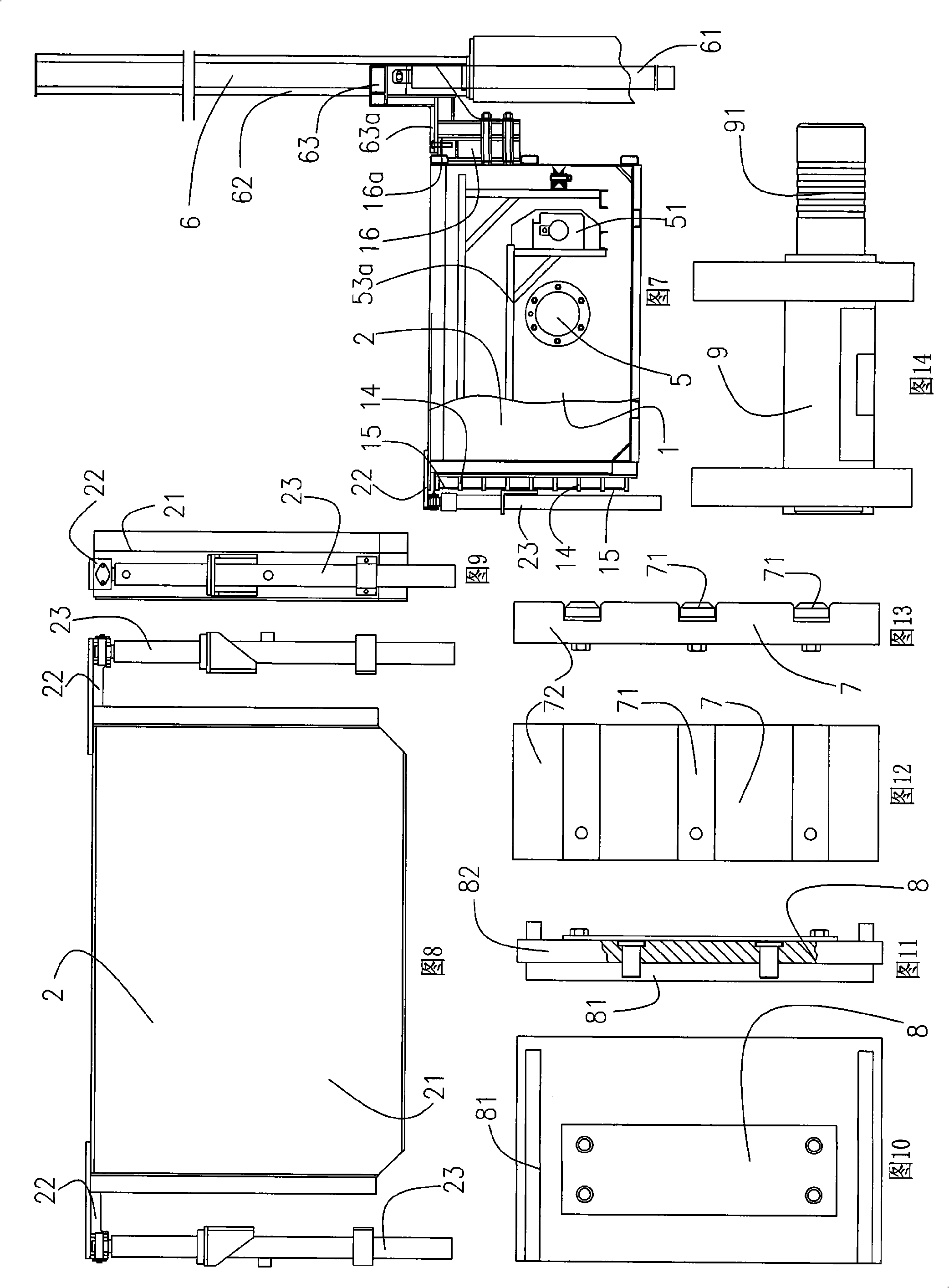
[0032] The structure of the present invention is shown in Fig. 1 to Fig. 14 . Explanation of icon numbers: garbage bin 1, discharge port 1a, feeding bin 1b, storage bin 1c, pushing bin 1d, surface layer body 11, side vertical plate 12, sewage hole 12a, reinforcing rib 12b, U-shaped groove body 13 , Buckle fixed plate 14, reinforcement plate 15, box lifting seat 16, top edge 16a, gate mechanism 2, gate 21, lifting lug 22, gate cylinder 23, rear top seat 3, push-out mechanism 4, push platform 41, the first A positioning body 41a, a rubbish block 41b, a push-out seat 42, a push-out cylinder 43, a push frame body 44, a rubbish-stop fixing plate 45, a rubbish-stop slide plate 46, a limit block 47, a compression mechanism 5, a compression seat 51, and a second positioning Body 51a, compression cylinder 52, mobile frame 53, bridge body 53a, lifting ...


PUM


Abstract

The invention provides a buried garbage compressor, comprising a garbage bin which is arranged in a pit; the front end of the garbage bin is provided with a material outlet; the middle position of the garbage bin is provided with a material pouring bin; the front end of the garbage box is provided with a gate mechanism which is provided with a gate arranged at the internal side of the material outlet; a material storage bin is formed between the gate and the material pouring bin; the top of the material storage bin is provided with a surface layer body; the rear end of the garbage bin is provided with a rear top base; a push pressing bin is formed between the rear top base and the material pouring bin; the push pressing bin is internally provided with a push-out mechanism and a compression mechanism which are connected with each other in a moving way; the compression mechanism is provided with a compression base; the rear end surface of the compression base is provided with a compression cylinder; furthermore, the compression cylinder is fixed on the rear top base; the prepositive gate with insertion structure is adopted; the garbage bin smartly moves up and down; a dual mechanism for compression and push-out is arranged; the whole machine has long service life; the design of a convex top block has high operation efficiency; the upper garbage baffle which slides by dual layers has good cleaning at the rear part of the garbage bin; an insurance mechanism is configured, thus the operation is safe.

Description

technical field [0001] The invention relates to the technical field of garbage compression machinery, in particular to an underground garbage compressor, which is suitable for garbage transfer treatment in densely populated areas such as towns and docks. Background technique [0002] At present, with the country's continuous emphasis on environmental protection and the improvement of people's living standards, in order to prevent garbage from polluting the surrounding environment, garbage needs to be pretreated by transfer equipment, which needs to be efficient and low-cost. Existing garbage compactor includes devices such as compression device, feeding hopper, hoisting device, such as the Chinese utility model patent "buried horizontal compression type garbage transfer station" (notification number is CN2716192) that is 200420036105.4 as the patent number is exactly this type of design. In this type of design, there is no front top door mechanism at the front of the pit, an...

Claims


Application Information

Patent Timeline
Patent Type & Authority Applications(China)
IPC IPC(8): B30B9/00B30B15/00
Inventor 石道凯
Owner 阮志华
Why Eureka
Try Eureka