
Method for manufacturing optical fiber current sensor sensitivity coil

A technology of sensitive coils and fiber optic currents, applied in the direction of voltage/current isolation, measuring current/voltage, instruments, etc., can solve the problems of fiber brittleness, long time, difficult processing such as welding, etc., to achieve easy processing, uniform speed, The effect of simple winding process

Active Publication Date: 2008-11-12
中国航天时代光电科技有限公司
View PDF2 Cites 23 Cited by
  • Summary
  • Abstract
  • Description
  • Claims
  • Application Information

AI Technical Summary

Problems solved by technology

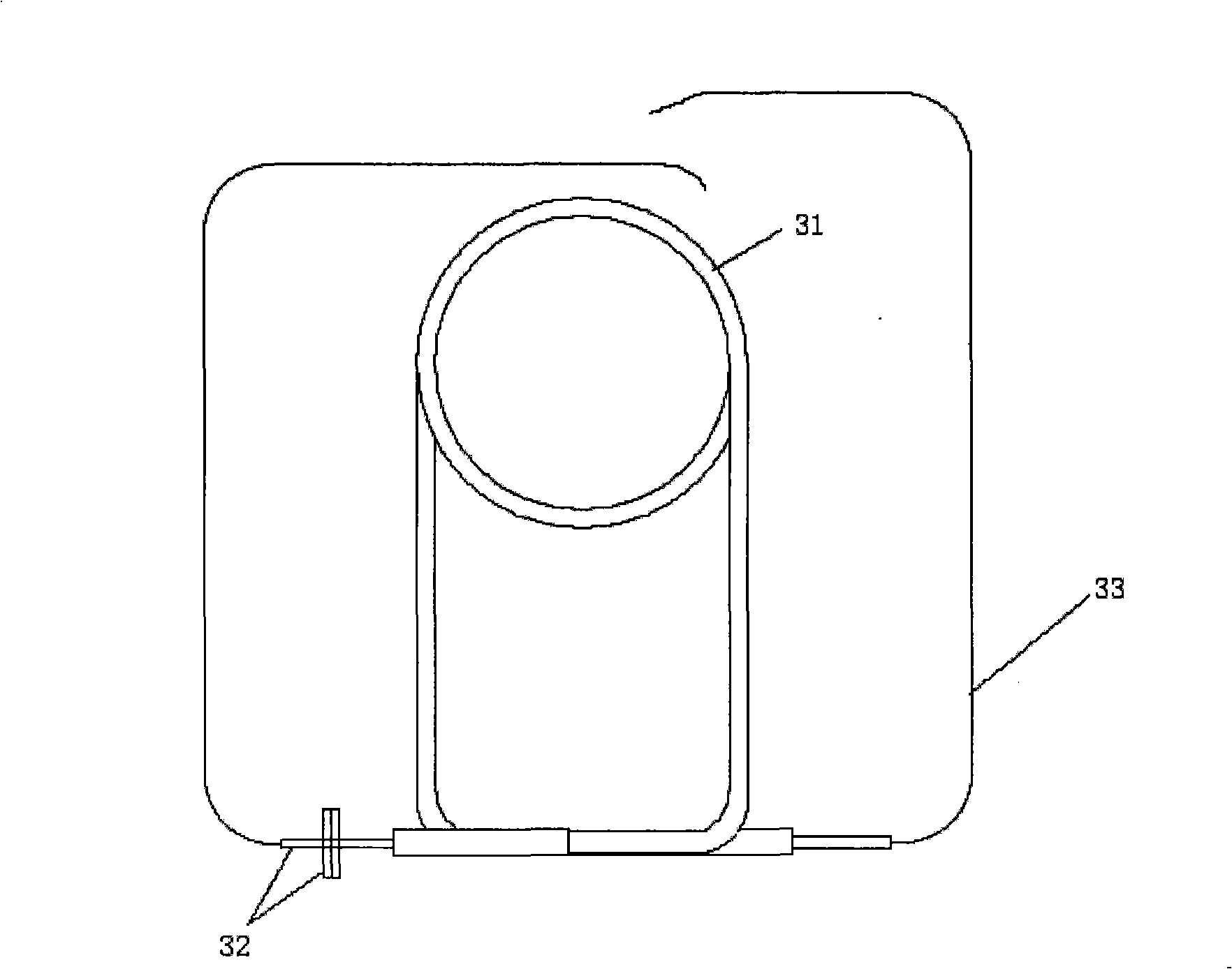
[0005] The 1997 patent No. CN1142265A "Faraday Effect Detection Coil with Stable Birefringence" discloses another method for preparing a sensitive coil. This method uses a coil 31 and a support frame 32 to fix the optical fiber 33, such image 3 As shown, the coil prepared by this method needs to be annealed, and annealing takes a long time, and will cause the optical fiber to become brittle, thus making subsequent processing such as welding difficult

Method used


Image

  • Method for manufacturing optical fiber current sensor sensitivity coil
  • Method for manufacturing optical fiber current sensor sensitivity coil
  • Method for manufacturing optical fiber current sensor sensitivity coil

Examples


Embodiment Construction

[0037] Such as Figure 5 As shown, it is a schematic diagram of the preparation method of the sensitive coil of the optical fiber current sensor of the present invention, among which 1 is a coil bobbin, 2 is an optical fiber, 3 is a symmetrical distribution point selected in the circumferential direction of the coil bobbin 1, 4 is the first quartz tube, 5 is the second quartz tube, 6 is the bracket, and 7 is the polarization-maintaining optical fiber.

[0038] First, the expansion coefficient is less than 10 -6 Or a material close to the optical fiber 2, such as quartz or Invar, prepares a ring-shaped coil bobbin 1, the outer diameter of the coil bobbin 1 is 20-200 cm, the inner diameter of the skeleton is 3-20 cm smaller than the outer diameter, and the height of the skeleton in the normal direction of the circle is 1-10 cm. In the embodiment of the present invention, the outer diameter of the coil frame 1 is selected to be 150 cm, the inner diameter is 140 cm, and the heigh...


PUM

PropertyMeasurementUnit
Outer diameteraaaaaaaaaa

Abstract

The invention discloses a method for preparing a sensor coil for an optical fiber current sensor, which comprises the steps that: (1) an annular coil frame is prepared with a relatively rough outer side surface, and an angle bracket is arranged on the outer side surface and the two sides of the angle bracket are both tangent with the coil frame; (2) the torsion of an optical fiber is removed to release stress; (3) the coil frame is fixed on the horizontal axis to ensure that the normal of the coil frame and the axes of the horizontal axis coincide and the horizontal axis of the coil frame is evenly rotated and fixed to fix the optical fiber on the coil frame; (4) symmetrical distributed points are chosen along the circumference direction of the coil frame to fix the optical fiber; (5) the two ends of the optical fiber are respectively provided with 1 / 4 wave plate and reflector and fixed on a bracket, the projection of the 1 / 4 wave plate and the reflector on the normal of the coil frame coincide and the end of the optical fiber provided with the 1 / 4 wave plate is connected with a polarization maintaining optical cable; (6) the coil is put into an incubator to remove stress introduced during the fixing process of the optical fiber; (7) the coil is fixed in a closed annular outer shell and sealed.

Description

technical field [0001] The invention relates to a method for preparing a coil, in particular to a method for preparing a sensitive coil of a reflective optical fiber current sensor. Background technique [0002] Optical fiber current sensor is a kind of photoelectric sensor based on Faraday effect and sensitive to the current passing in the conductor. Because of its advantages of high voltage insulation, high safety and reliability, and low maintenance cost, it has a good market prospect. Some products have begun to be applied. In the development and production, the main problem of the reflective interference fiber optic current sensor is to ensure the accuracy, that is, the long-term stability of the proportional factor, which is mainly guaranteed by high-quality sensitive coils. [0003] The article "Temperature and Vibration Insensitive Fiber-Optic Current Sensor" in the second issue of "JOURNAL OF LIGHTWAVE TECHNOLOGY" in volume 20 in 2002 discloses a method for prepari...

Claims


Application Information

Patent Timeline
IPC IPC(8): G01R15/24G01R19/00
Inventor 王巍张志鑫王学锋
Owner 中国航天时代光电科技有限公司
Learn More