
Photon band-gap double-folding dipole dual frequency band antenna

A technology of folded dipoles and photonic bandgap, which is applied to the combination of antennas and antenna units with different polarization directions, and devices that make antennas work in different bands at the same time, can solve problems that have not been reported before, and achieve omnidirectional radiation Excellent performance, large bandwidth and simple structure

Inactive Publication Date: 2012-01-04
XIAMEN UNIV
View PDF0 Cites 4 Cited by
  • Summary
  • Abstract
  • Description
  • Claims
  • Application Information

AI Technical Summary

Problems solved by technology

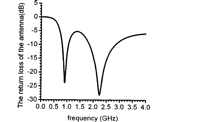
At present, the double folded dipole antenna is combined with the PBG structure to achieve dual-band operation, and it is applied in the RFID system and 3G system mobile terminals in the three working frequency bands of 0.902-0.928GHz, 1.92-2.17GHz and 2.4-2.4835GHz. Related technologies have not been reported

Method used


Image

  • Photon band-gap double-folding dipole dual frequency band antenna
  • Photon band-gap double-folding dipole dual frequency band antenna
  • Photon band-gap double-folding dipole dual frequency band antenna

Examples


Embodiment Construction

[0021] The present invention will be further described below in conjunction with embodiments and accompanying drawings.

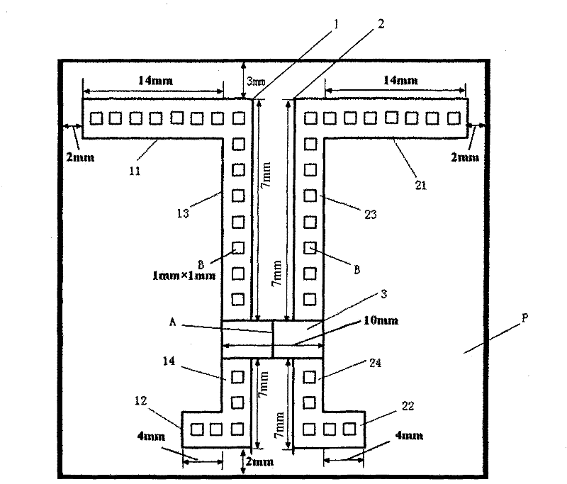
[0022] see figure 1 , the present invention is provided with a single-sided copper-clad dielectric substrate P, and the copper-clad area is provided with a left-right folded dipole radiation patch 1 and a right-folded dipole radiation patch 2 and a left-folded dipole radiation patch with the same structure and size. Dipole radiating patch and right folded dipole radiating patch are connected horizontally connecting patch 3; left folded dipole radiating patch 1 is located on the left side of dielectric substrate P, right folded dipole radiating patch 2 is located in On the right side of the substrate P, the connection patch 3 is located between the left folded dipole radiation patch 1 and the right folded dipole radiation patch 2; the left folded dipole radiation patch 1 and the right folded dipole radiation patch There is a space between 2, and there is a ...


PUM


Abstract

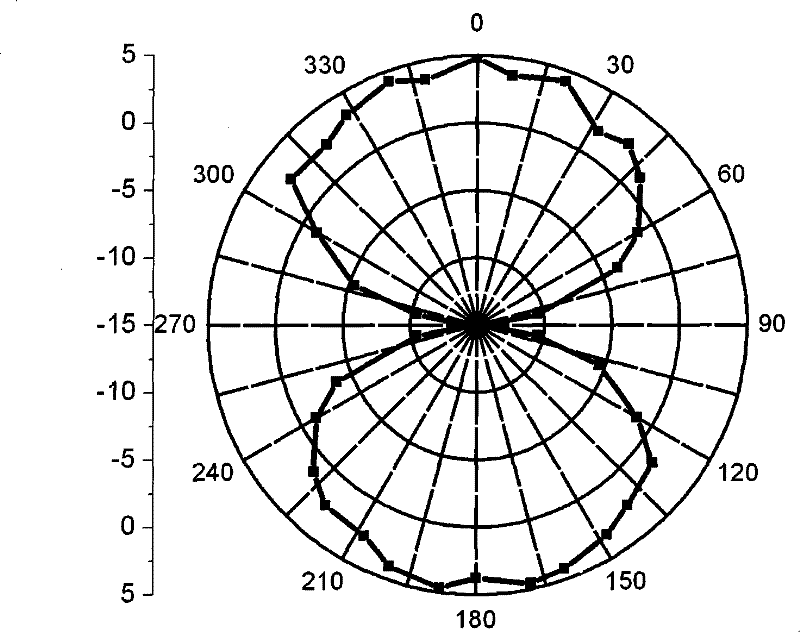
The invention discloses a photon band-gap double folding dipole double frequency band antenna, relating to a microstrip antenna. The invention provides a photon band-gap double folding dipole double frequency band antenna of a movable terminal of a compatible radio frequency identification system and a 3G system, which has small size, large bandwidth, lower return loss and omidirectional radiation characteristics; the antenna is provided with a medium base plate with one surface bonded with copper, and in the area which is bonded with copper, a left folding dipole radiation patch, a right folding dipole radiation patch and a connecting patch which is connected with the left folding dipole radiation patch and the right folding dipole radiation patch are arranged, wherein the left folding dipole radiation patch and the right folding dipole radiation patch have the same structure; the left folding dipole radiation patch is positioned at the left side of the medium base plate and the right folding dipole radiation patch is arranged at the right side of the medium base plate; the connecting patch is positioned between the left folding dipole radiation patch and the right folding dipole radiation patch.

Description

technical field [0001] The invention relates to a microstrip antenna, in particular to a photon bandgap double-folded dipole dual-band antenna for radio frequency identification technology and 3G system mobile terminals. Background technique [0002] Radio frequency identification (RFID) technology is a non-contact automatic identification technology realized by radio frequency communication that emerged in the 1990s. RFID tags have the characteristics of small size, large capacity, long life, and reusability. They can support fast reading and writing, non-visual identification, mobile identification, multi-target identification, positioning and long-term tracking management. Combined with other technologies, it can be used in logistics, manufacturing, public information services and other industries to achieve efficient management and operation and reduce costs. With the continuous improvement and maturity of security soft information-related technologies, the RFID series ...

Claims


Application Information

Patent Timeline
Patent Type & Authority Patents(China)
IPC IPC(8): H01Q1/38H01Q5/00H01Q13/08H01Q21/24H01Q5/20
Inventor 游佰强林斌徐伟明周建华刘舜奎施芝元李伟文
Owner XIAMEN UNIV
Learn More