Supercharge Your Innovation With Domain-Expert AI Agents!

Method and device for fault localization and safety prevention detection using passive optical network

A passive optical network and fault location technology, which is applied to the selection device of the multiplexing system, the use of optical devices to transmit sensing components, and selection devices, etc., can solve the problems that security monitoring cannot be realized, and achieve high sensitivity and high The effect of accuracy

Inactive Publication Date: 2008-11-12
UNIV OF ELECTRONIC SCI & TECH OF CHINA
View PDF0 Cites 40 Cited by
  • Summary
  • Abstract
  • Description
  • Claims
  • Application Information

AI Technical Summary

Problems solved by technology

Therefore, although distributed sensing technology is used, since the back Rayleigh scattered light of each branch overlaps together and cannot be separated, and the sensing light source is a broadband light source, it can only monitor the optical cable fault in the PON structure, not Realize security monitoring function

Method used


Image

  • Method and device for fault localization and safety prevention detection using passive optical network
  • Method and device for fault localization and safety prevention detection using passive optical network
  • Method and device for fault localization and safety prevention detection using passive optical network

Examples


Embodiment

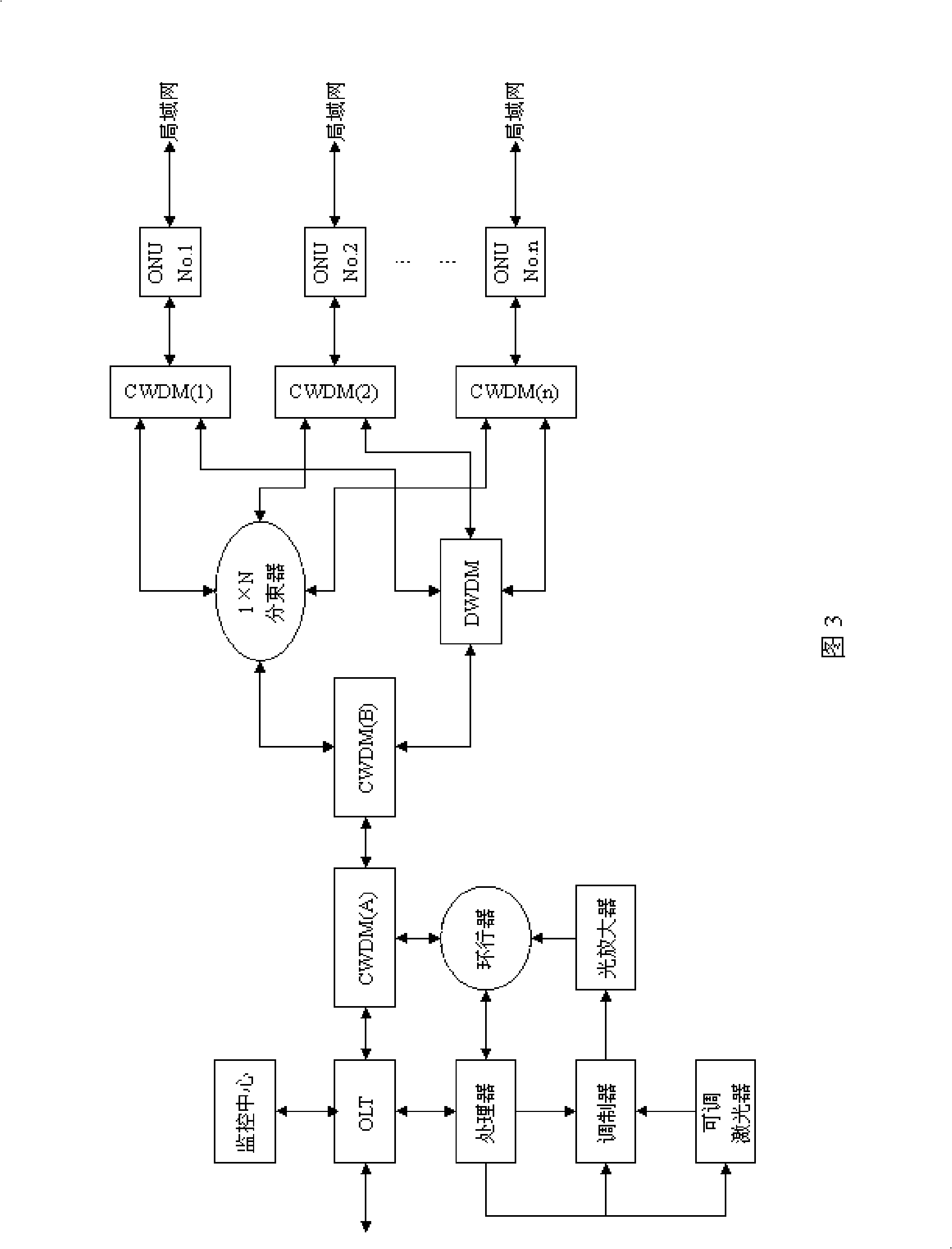
[0036] The structure of the system in this example is shown in Figure 3. This example uses a high-performance, low-cost tunable laser, which has the characteristics of narrow linewidth, high extinction ratio, stable central wavelength and fast response speed. The tunable laser can be controlled by the processor in real time, and periodically emit wavelengths of λ according to the set time interval 1 , lambda 2 ... λ n The laser signal is used as the sensing light source.

[0037] At a specific moment, the tunable laser emits a wavelength of λ n After the sensing laser is modulated by the modulator, it is coupled with the normal downlink communication laser through CWDM (A) and then connected to the PON trunk optical cable. The modulator also communicates with the processor to facilitate program control to adjust the width and repetition frequency of the modulated pulse to adjust the intrusion detection accuracy and maximum monitoring distance.

[0038] After the modulated...


PUM


Abstract

The invention relates to a distributed optical fiber sensor, which aims at the defect that the PON sensing system of the prior art cannot distinguish sensing information of each ONU branch. The invention discloses a method of using a passive optical network to do fault location and security-monitoring detection and a device thereof. The method of using the passive optical network to do fault location and security-monitoring detection comprises the following steps: a. sensing lasers with different wavelengths are injected into the PON according to a certain time interval; b. the sensing lasers with different wavelengths are correspondingly injected into each ONU branch at an ONU access end; c. the returned back Raleigh scattering lights from each ONU branch are received; d. the OTDR treatment to the received back Raleigh scattering lights is carried out. The invention also discloses the device of using the passive optical network to do fault location and security-monitoring detection. The invention can be applied in the fault location and security-monitoring detection in the PON system.

Description

technical field [0001] The invention relates to a distributed optical fiber sensor, in particular to a fault location and security detection method and device in a passive optical network (PON). Background technique [0002] Next-Generation Network (NGN) and Next-Generation Internet (NGI) are a comprehensive open network architecture that can provide various services. The five "medium- and long-term science and technology planning focuses on supporting directions, among which access network technology and switching technology are the focus of NGN and NGI research. The trend of "light into copper" in my country is accelerating, point-to-point applications for commercial users have become increasingly popular, PON has become FTTB, FTTC, FTTO, FTTH (fiber access technology, collectively referred to as FTTx, including Fiber to the building, Fiber to the curb, Fiber to the office, Fiber to the home). The current mainstream PON includes Ethernet PON (EPON for short) and Gigabit P...

Claims


Application Information

Patent Timeline
IPC IPC(8): H04B10/08H04Q11/00G01D5/26H04B10/077
Inventor 饶云江冉曾令熊森罗力伟
Owner UNIV OF ELECTRONIC SCI & TECH OF CHINA
Features
  • R&D
  • Intellectual Property
  • Life Sciences
  • Materials
  • Tech Scout
  • Unparalleled Data Quality
  • Higher Quality Content
  • 60% Fewer Hallucinations
Learn More