
Continuous fibrous globule filter and its filtering method

A technology of fiber balls and filters, applied to loose filter material filters, filtration separation, separation methods, etc., can solve whether compaction and compaction are different, difficult to control, difficult to completely remove dirt, and unable to achieve loosening, etc. problems, to achieve the effect of easy automatic control, water content reduction, and easy cleaning

Inactive Publication Date: 2008-11-19
北京市农业机械研究所有限公司
View PDF0 Cites 7 Cited by
  • Summary
  • Abstract
  • Description
  • Claims
  • Application Information

AI Technical Summary

Problems solved by technology

[0010] At present, the existing fiber ball sewage filtration technology has the following shortcomings: because the fiber ball is a radial sphere, the fibers near the center of the ball are dense, and it cannot be loosened during backwashing, and the retained dirt is difficult to completely remove;
[0011] When the inlet water quality is different and the outlet water quality requirements are different, it is difficult to control whether the compaction and the compaction amount are different;
[0012] It cannot be processed continuously, and backwashing must be carried out, which is a waste of time;
[0013] It is not easy to implement automatic control;

Method used

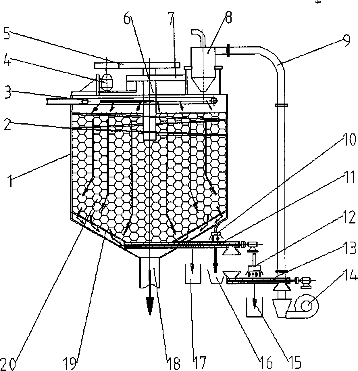
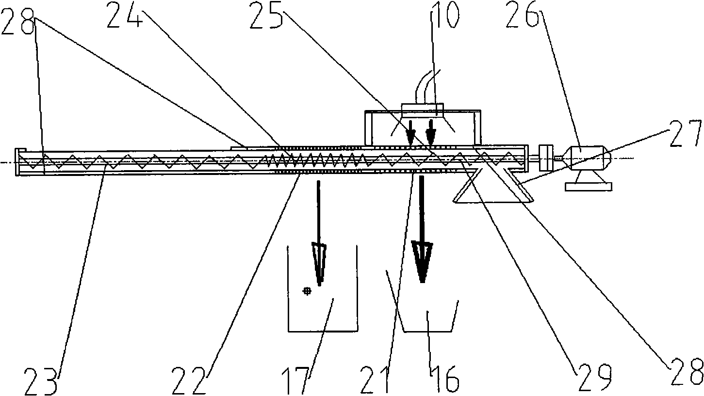
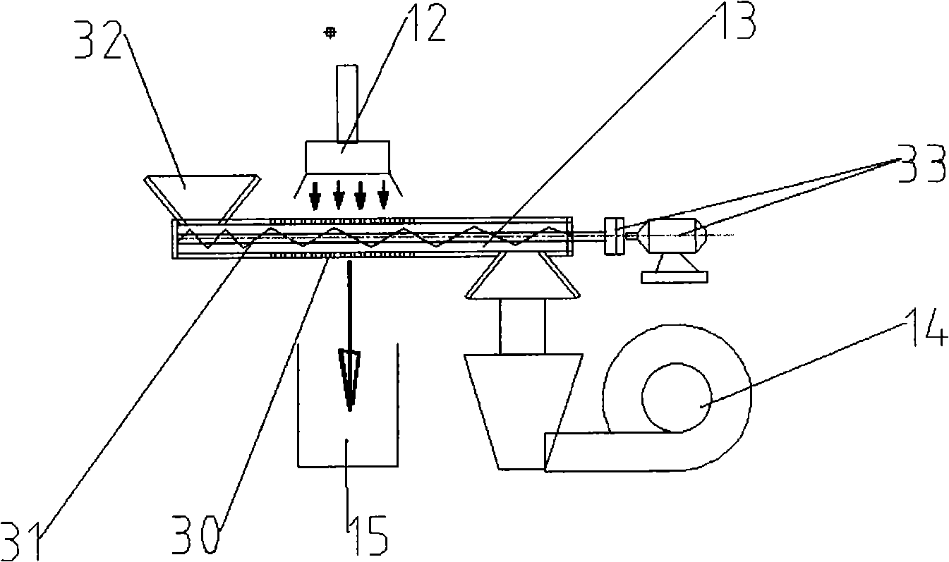

Image

  • Continuous fibrous globule filter and its filtering method
  • Continuous fibrous globule filter and its filtering method
  • Continuous fibrous globule filter and its filtering method

Examples


Embodiment 1

[0030] exist figure 1 Among them, the frame 7 is installed on the upper end surface of the housing 1 with bolts. The pressing and conveying screw shaft 6 is fixed on the frame 7 with a bearing seat, and is concentric with the center line of the cylindrical body 1. The compression conveying screw 2 is welded on the compression conveying screw shaft 6, the screw is not less than two turns, the total height of the screw is not greater than one-fifth of the cylindrical part of the shell, and the annular gap between the outer diameter of the spiral and the inner surface of the shell is less than 5mm, with 5mm through holes evenly distributed on the helical surface. Compress conveying screw motor 4 and be fixed on the frame 7 with screw pair. The driving shaft and the output shaft of the pressing and conveying screw reduction mechanism 5 are respectively connected with the pressing and conveying screw motor 4 and the pressing and conveying screw shaft 6 .

[0031] The sewage dist...

Embodiment 2

[0038] exist figure 1 The sewage can enter from the bottom, and the sewage distribution pipe 3 is installed at the junction of the cone and the cylinder of the housing 1, the sewage is filtered during the upward floating process, and the clean water overflows from the upper part of the housing 1.


PUM


Abstract

A continuous fiber ball filtering machine and a filtering method belong to the technology filed of sewage filtration. The continuous fiber ball filtering machine comprises a continuous fiber ball filtering machine main body, a fiber ball cleaning system and a fiber ball sending-back system. A feed inlet of the fiber ball cleaning system is welded at the lower part of the continuous fiber ball filtering machine main body, the feed inlet of the fiber ball sending-back system needs to be aligned with a discharge outlet of the fiber ball cleaning system, and a discharger of the fiber ball sending-back system is arranged at the upper end surface of the continuous fiber ball filtering machine main body. The continuous fiber ball filtering machine has the advantages that the filter has the independent filtering ball cleaning system and the sending-back system, thereby realizing the continuous filtration; a step of dirty filtering ball squeezing is added, most of the sewage in the filtering ball can be squeezed in the step; a step of air flow cleaning is added, the sludge blown by the air flow is easier to concentrate in the situation that the sewage in the filtering ball is squeezed out, the air flow is used for carrying out the flush after the squeezing and the air flow cleaning, thereby reducing the water consumption for back flush; and the automatic control is easy to realize.

Description

technical field [0001] The invention belongs to the technical field of sewage filtration, and in particular provides a continuous fiber ball filter and a filtering method thereof. Background technique [0002] The fiber ball is made of fiber silk as raw material and ligated by a special process. Compared with the filter bed made of rigid granular filter materials such as traditional quartz sand, the filter bed made of fiber balls has the following characteristics: [0003] The fiber ball filter is filled with fiber balls in the container to form a bed. Since the individual fiber balls are relatively loose, the fiber filaments between the fiber balls in the bed can be interspersed with each other. At this time, the individual characteristics of the fiber balls are not important. The bed forms a whole. In an unpressurized bed, the pressure on the fiber ball is the sum of the fluid resistance of the filtered water flow, the weight of the fiber ball itself, and the gravity of ...

Claims


Application Information

Patent Timeline
IPC IPC(8): B01D24/12
Inventor 邹岚白洪涛
Owner 北京市农业机械研究所有限公司
Learn More