Sea floor architecture positioning apparatus and method

A technology for positioning devices and buildings, applied in buildings, underwater structures, water conservancy projects, etc., can solve the problems of small blade area, insufficient anchoring force, large machinery construction investment, etc., to achieve less construction investment machinery and easy operation , the effect of short construction period

Inactive Publication Date: 2008-11-19
TONGJI UNIV
View PDF0 Cites 11 Cited by
  • Summary
  • Abstract
  • Description
  • Claims
  • Application Information

AI Technical Summary

Problems solved by technology

The commonly used anchoring method is mainly the spiral anchor method. The main disadvantage is that the blade area is small, the anchoring force generated by it is not large enough, and it requires a large investment in mechanical construction.

Method used


Image

  • Sea floor architecture positioning apparatus and method
  • Sea floor architecture positioning apparatus and method
  • Sea floor architecture positioning apparatus and method

Examples


Embodiment Construction

[0031] The implementation of the present invention will be described in detail below in conjunction with the accompanying drawings.

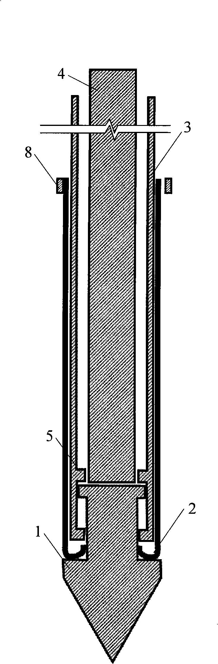
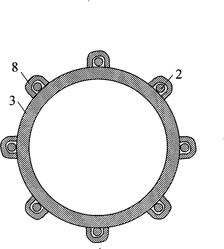
[0032] figure 1 The situation of the present invention when the anchor parachute is tightened is illustrated. The bottom of the anchor point 1 is conical, which is beneficial for breaking through the soil and entering the mud. The anchor umbrella skeleton 2 is arranged around the step in the middle of the anchor point 1, and the upper end of the anchor umbrella skeleton 2 can be inserted into the anchor umbrella skeleton jack 8 arranged on the outer wall of the anchor rod 3. The schematic diagram of the layout of the anchor umbrella skeleton jack 8 is shown in image 3 . The anchor umbrella skeleton 2 has a spring structure with greater toughness at its root, which can provide a strong outward elastic force for the automatic opening of the anchor umbrella, while the straight section of the skeleton is a rigid steel wire, and the anchor umbrel...


PUM


Abstract

The invention discloses a positioning device for a submarine building, consisting of an anchor bar and an anchor umbrella, wherein, the anchor umbrella is positioned at the bottom of the anchor bar; the open anchor umbrella takes the shape of an inversed umbrella. During the process of submarine sinking, the anchor umbrella is folded tightly, and a framework of the anchor umbrella of the positioning device is separated from a jack and stretched out in the shape of the umbrella until the predetermined position is reached. The power of the positioning device for injecting into the seabed is vibration of a high-frequency micro-amplitude vibration source which is arranged on the top of the anchor bar, and the vibration frequency is more than 50 hertzs. Under the action of high-frequency micro-amplitude vibration, a hardened silt structure is damaged, generates liquefaction and forms slurry with fluidness, thereby the device can run through smoothly; and silt with fluidness is easy to pass through an open screen of the anchor umbrella so as to make the anchor umbrella automatically open. After the anchor umbrella is opened, a large-area structural plane is formed; and the deadweight of soil bodies on the upper part of the structural plane provides strong anti-floating force, and soil bodies on the lower part of the structural plane limit the sinking action of the positioning device. The positioning device for the submarine building has simple construction technique, easy operation, short construction period and low manufacturing cost.

Description

technical field [0001] The invention relates to building positioning technology, in particular to a positioning device and method for fixing submarine structures, belonging to the field of marine engineering. Background technique [0002] With the depletion of earth's terrestrial resources, the world today pays more and more attention to the development of marine resources. In order to move towards the sea, a large number of buildings must be built on the seabed, mainly including permanent buildings and temporary buildings. For example, the submarine pipelines that transport oil and gas are permanent submarine structures, while a large number of deep-sea observation devices distributed in the seas of various countries are temporary structures. No matter what kind of buildings, they are all located on the seabed where the water depth is large, the conditions are harsh, and it is difficult to observe. Therefore, the safety and stability of submarine buildings have always been...

Claims


Application Information

Patent Timeline
Patent Type & Authority Applications(China)
IPC IPC(8): E02D29/09E02D5/74
Inventor 谢立全
Owner TONGJI UNIV
Why Eureka
Try Eureka