
Energy-storing and releasing device for braking

A flywheel device and energy technology, applied in the direction of transmission, belt/chain/gear, mechanical equipment, etc., can solve the problems of large space occupation, uncompact structure, and increased cost

Inactive Publication Date: 2008-11-19
陆中源
View PDF1 Cites 1 Cited by
  • Summary
  • Abstract
  • Description
  • Claims
  • Application Information

AI Technical Summary

Problems solved by technology

Compared with the above-mentioned two kinds of hybrid electric buses, the "old braking flywheel device" has the advantages of energy-saving and pollution-reducing effect as good or better, and low cost. The main disadvantage of greater difficulty needs to be improved

Method used


Image

  • Energy-storing and releasing device for braking
  • Energy-storing and releasing device for braking
  • Energy-storing and releasing device for braking

Examples


Embodiment Construction

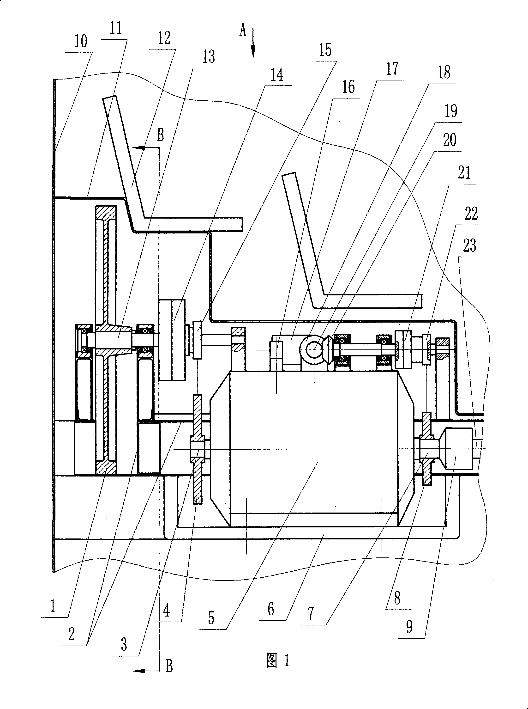
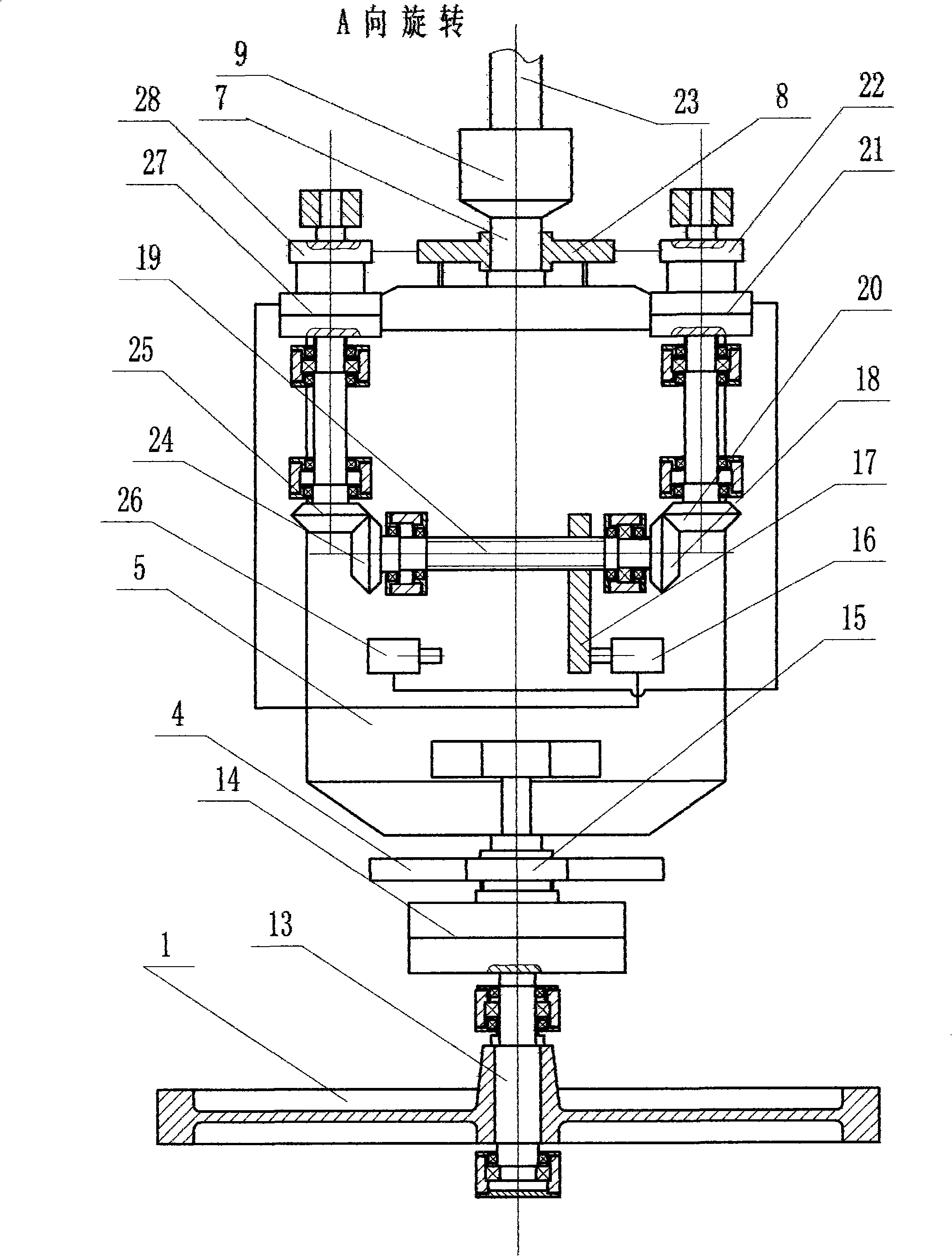
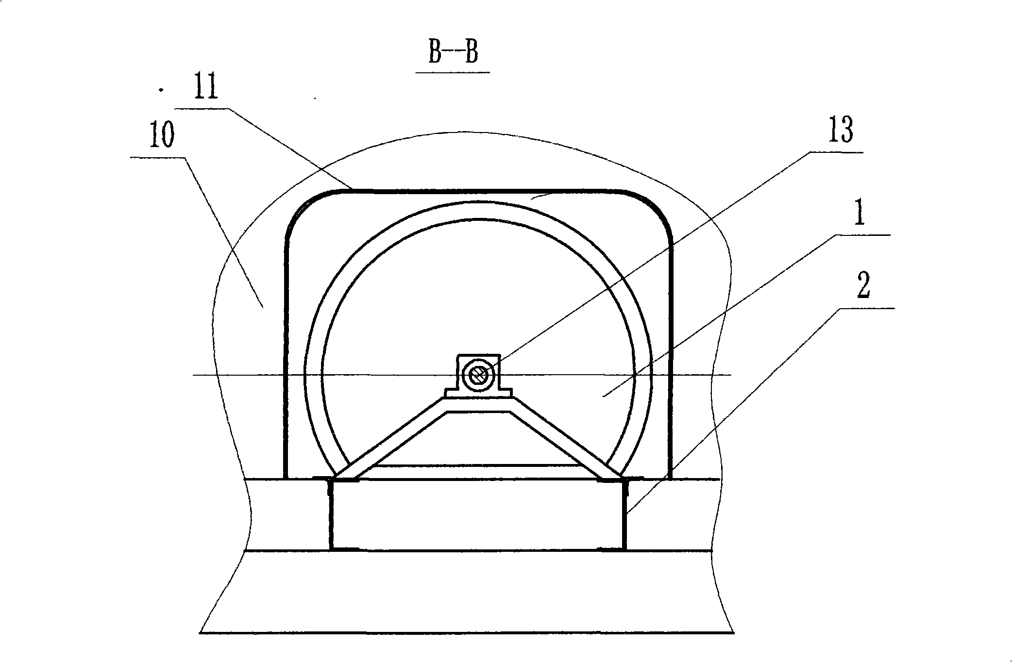
[0005] As can be seen from Figs. 1 and 2, the present embodiment has a flywheel (1), a power input and output outer shaft (23) and a speed ratio adjusting device with the flywheel (1), and is characterized in that: the flywheel (1) and the continuously variable transmission ( 5) input shaft (3) transmission connection; the power input and output outer shaft (23) is connected with the output shaft (7) of the continuously variable transmission (5); the speed ratio adjustment device of the continuously variable transmission (5) is the power input and output external The speed ratio adjusting device of axle (23) and flywheel (1). The process of storing energy in this device: the speed ratio adjusting device of manipulating the power in and out of the outer shaft (23) and the flywheel (1), so that the speed ratio i of the output shaft (7) and the input shaft (3) of the continuously variable transmission (5) is changed by If the size becomes smaller, the rotating speed of the output...


PUM


Abstract

The invention discloses a mechanical drive device for storing and releasing energy in braking. The mechanical drive device comprises a flywheel(1), a power input-output outer shaft (23) and an speed ratio adjusting device for the power input-output outer shaft (23) and the flywheel (1), wherein the flywheel (1) is in transmission connection with an input shaft (3) of a continuously variable transmission (5). The power input-output outer shaft (23) is in transmission connection with an output shaft (7) of the continuously variable transmission (5). The speed ratio adjusting device of the continuously variable transmission (5) is also the speed ratio adjusting device for the power input-output outer shaft (23) and the flywheel (1), so the speed ration i of the continuously variable transmission (5) is adjusted by adjusting the speed ratio of the power input-output outer shaft to the flywheel. After power units such as motor vehicles, etc. requiring breaking are connected with the power input-output shaft (23), the mechanical drive device realizes braking energy storage while the i reduces; otherwise, the mechanical drive device realizes braking energy release while the i increases. Compared with similar devices, the device has the advantages of remarkable energy saving and pollution reducing effect, compact structure taking up small space volume, simplness, reliability and low cost, and is easy to popularize and use.

Description

technical field [0001] The invention relates to power mechanical devices, especially brake energy-saving mechanical devices for motor vehicles and lifting equipment. Background technique [0002] For a long time, how to recover the kinetic energy of power equipment (especially motor vehicles) with high efficiency and low cost has been a major energy-saving problem in the machinery industry for a long time. Two kinds of so-called " hybrid electric buses " have occurred in recent years, and a kind of is the bus that has installed braking storage energy hydraulic system additionally, and another kind is the bus that has installed braking storage energy electric system additionally. When braking to decelerate or going downhill, the driving kinetic energy or potential energy of the two vehicles is converted into hydraulic energy or electric energy and stored in the hydraulic accumulator or battery; when the vehicle starts or accelerates, the energy stored in the brake is first re...

Claims


Application Information

Patent Timeline
Patent Type & Authority Applications(China)
IPC IPC(8): F16H33/02
Inventor 陆中源
Owner 陆中源
Learn More