
Method for measuring optical non-linear 4f phase coherent imaging

An optical nonlinear and phase coherent technology, applied in the field of nonlinear photonics materials and nonlinear optical information processing, can solve the problems of the surface of the easily damaged medium, affecting the accuracy of the measurement, the inapplicability of optical nonlinearity, etc. The effect of accuracy, accurate test results and convenient measurement

Inactive Publication Date: 2008-11-19
SUZHOU UNIV
View PDF0 Cites 20 Cited by
  • Summary
  • Abstract
  • Description
  • Claims
  • Application Information

AI Technical Summary

Problems solved by technology

However, the above-mentioned measurement methods measure the optical nonlinearity of the medium by measuring the change of the transmitted light, which is not suitable for the medium with low transmittance and the study of the optical nonlinearity of the surface of the medium.
[0004] In 1994, D.V.Petrov and others proposed a reflection Z-scan method that can measure the optical nonlinearity of the medium surface (D.V.Petrov, A.S.L.Gomes, and Cid B.de Arabjo, "Reflection Z-scantechnique for measurements of optical properties of surfaces", Appl .Phy.Lett., 65, 1067 (1994)), this method is the same as the traditional transmission Z-scanning method, which requires the movement of the sample in the direction of laser propagation and multiple laser excitations, which is easy to damage the surface of the medium. The measurement of reflected light, and the reflective surface has to move during the measurement process, which increases the difficulty of measurement and affects the accuracy of measurement

Method used


Image

  • Method for measuring optical non-linear 4f phase coherent imaging
  • Method for measuring optical non-linear 4f phase coherent imaging
  • Method for measuring optical non-linear 4f phase coherent imaging

Examples


Embodiment 1

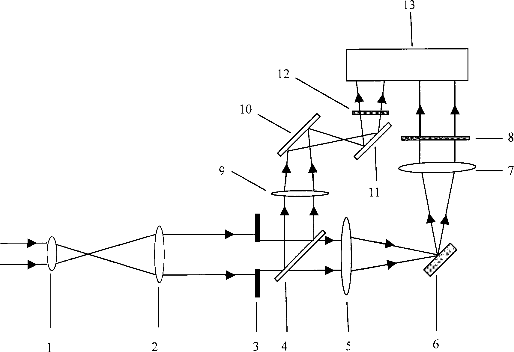
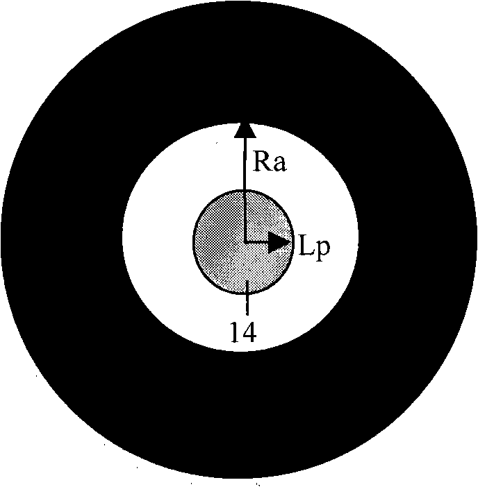
[0028] Embodiment one: attached figure 1 It is the experimental setup diagram of the reflective 4f phase coherent imaging system for measuring the optical nonlinearity of the medium. The experimental setup can be divided into three parts: beam expander system, measurement system and reference system. The beam expander system is composed of a convex lens 1 and a convex lens 2; the measurement system is composed of a phase diaphragm 3, a first convex lens 5, a sample to be measured 6, a second convex lens 7, a neutral attenuation film 8 and a CCD camera 13. Wherein the neutral attenuation film 8 is used to ensure that the CCD camera 13 is within its linear response, the first convex lens 5 and the second convex lens 7 constitute a reflection 4f system, and the phase diaphragm 3 is placed on the object surface of the reflection 4f system, and the sample to be tested 6 On the Fourier plane, the CCD camera 13 receives the spot image on the image plane of the 4f system. The pulsed...


PUM

PropertyMeasurementUnit
refractive indexaaaaaaaaaa

Abstract

The invention discloses a method which can measure the optical nonlinearity of a medium interface and apply the reflected light to measure the film optical nonlinearity, which belongs to the nonlinear photonics material and nonlinear optical information processing fields. An incident laser light is divided into two ways through a beam splitting prism, one way is a probe light which enters a measure optical path and is collected by a CCD camera after passing through a 4f phase coherent imaging system; and the other way is a reference light; and the method is characterized in that: the sample is placed on a focal plane of a first convex lens of the measure optical path in a reflection mode, a second convex lens having the same focal length with the first convex lens is positioned at the one-time focal length part along the transmission direction of the reflected light, thereby forming the reflection 4f phase coherent imaging system; and the measurements include two parts of energy calibration and optical nonlinearity measurement. The method has the advantages of convenient measurement, simple optical path, non movement of sample, single pulse measurement, being not easy to damage medium surfaces, and having low requirements to stability of light source energy and space.

Description

technical field [0001] The invention relates to a method for measuring the nonlinear properties of materials by using optical means, in particular to a method for measuring the optical nonlinearity of medium interface reflection based on reflection 4f phase coherent imaging technology and the method for measuring the optical nonlinearity of thin films by using reflected light. In the field of linear photonic materials and nonlinear optical information processing. Background technique [0002] With the rapid development of technologies in the fields of optical communication and optical information processing, the research on nonlinear optical materials is becoming increasingly important. The realization of functions such as optical logic, optical memory, optical transistor, optical switch and phase complex conjugation mainly depends on the research progress of nonlinear optical materials. Optical nonlinear measurement technology is one of the key technologies for studying no...

Claims


Application Information

Patent Timeline
Patent Type & Authority Applications(China)
IPC IPC(8): G01N21/45G01N21/17
Inventor 宋瑛林杨俊义李云波顾济华王玉晓
Owner SUZHOU UNIV
Learn More