Constant temperature keeping device

A technology of constant temperature and generation device, which is used in household refrigeration devices, cooling fluid circulation devices, temperature control and other directions, can solve the problems of slow heat conduction of cold medium gas and increased burden on heaters, and achieves improved thermal responsiveness and thermal response. high sex effect

Inactive Publication Date: 2008-11-26
ATS JAPAN CORP
View PDF3 Cites 24 Cited by
  • Summary
  • Abstract
  • Description
  • Claims
  • Application Information

AI Technical Summary

Problems solved by technology

However, the heat conduction speed of the cold medium gas (Freon gas, etc.) in the refrigeration cycle system of the cooler is slow, so it often happens that the set temperature is greatly exceeded (overshoot), or the set temperature is greatly lower than the set temperature. (low-key downshoot) case
This increases the burden on the heater, requiring a large heater capable of temperature adjustment over a wide temperature range

Method used


Image

  • Constant temperature keeping device
  • Constant temperature keeping device
  • Constant temperature keeping device

Examples


Embodiment 1

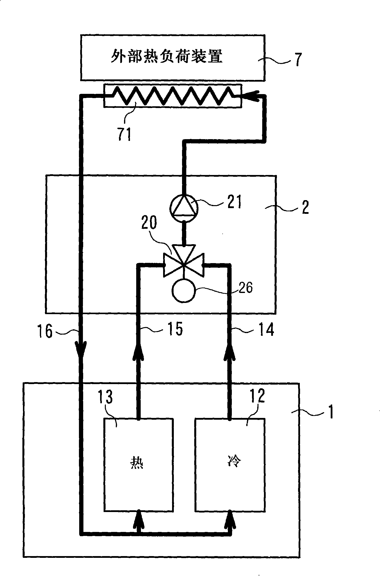
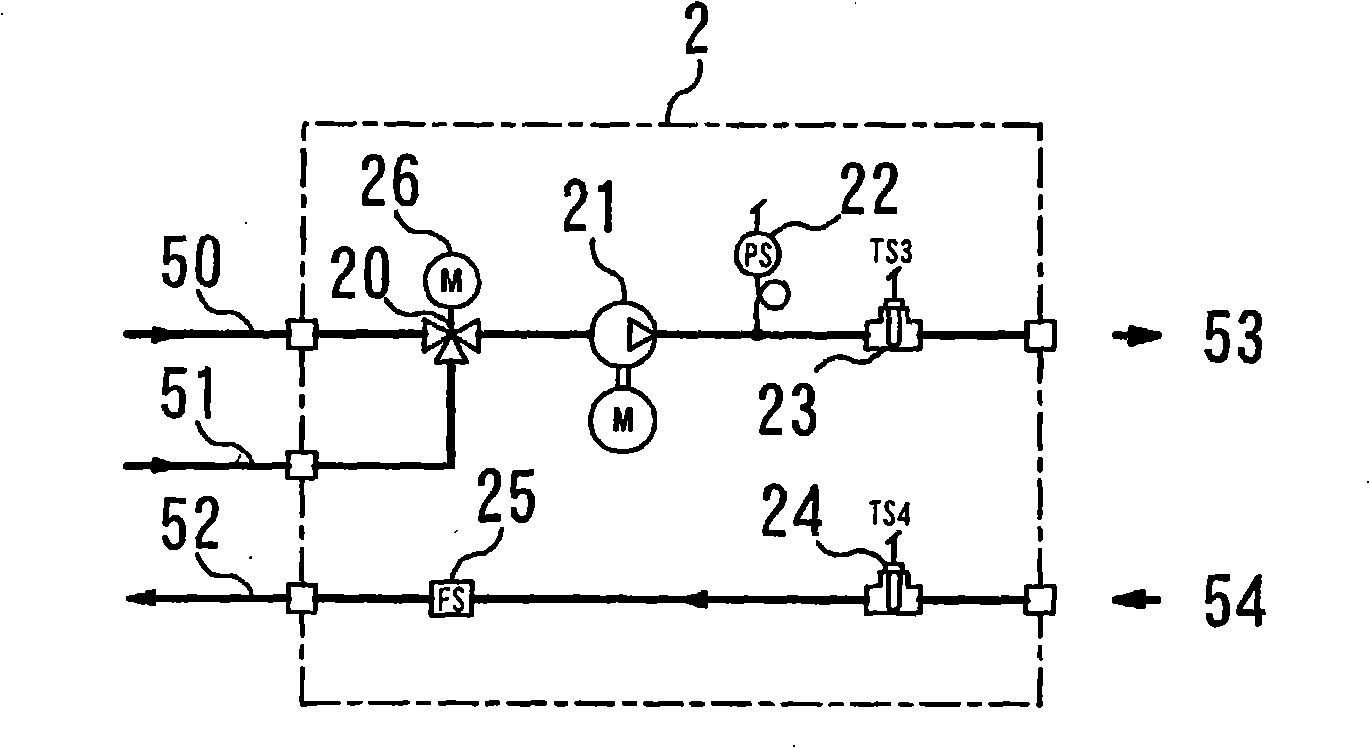
[0074] figure 1 It is a conceptual diagram showing the constant temperature maintaining device of the present invention, 1 is a main unit, 2 is an auxiliary unit, 12 is a low-temperature heat medium circulating fluid generator, 13 is a high-temperature heat medium circulating fluid generator, 20 is a three-way valve, 21 is a 26 is a control valve, 7 is an external heat load device, and 71 is a heat exchange chamber.

[0075] The low-temperature heat medium circulating fluid generated by the low-temperature heat medium circulating fluid generator 12 is supplied to the auxiliary unit through the high-temperature circulating fluid supply pipe 15 through the low-temperature circulating fluid supply pipe 14 , and the high-temperature heat medium circulating fluid generated by the high-temperature heat medium circulating fluid generator 13 is supplied to the auxiliary unit through the high-temperature circulating fluid supply pipe 15 2 three-way valve 20. The control valve 26 of th...

Embodiment 2

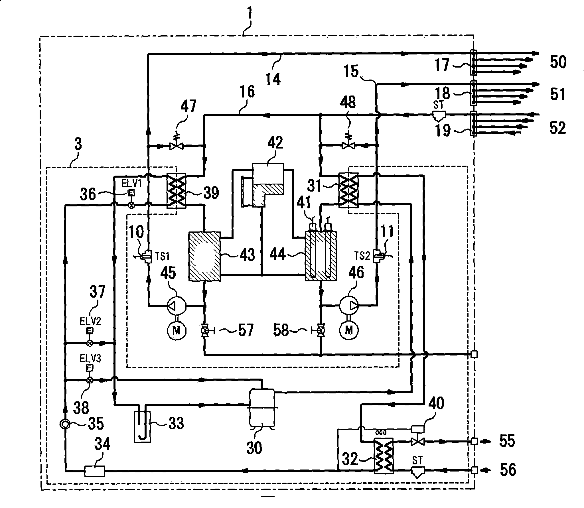
[0113] FIG. 11 shows an example in which plant water is used as a cooling source of the main unit and a heater is used as a heating source.

[0114] 4 is the factory equipment water cooling system, the factory water introduced from the cooling water inlet 56, in the equipment water heat exchanger 59, exchanges heat with the low-temperature circulating fluid returned from the auxiliary unit 2 through the pipe 16, thereby cooling Low temperature circulating fluid. The cooled low-temperature circulating fluid is stored in the cooling side tank 43 , passed through the low-temperature circulating fluid supply pipe 14 by the cooling pump 45 , and sent to the auxiliary unit 2 through the low-temperature circulating fluid auxiliary unit supply pipe 50 . The temperature of the low-temperature circulating fluid is measured by the cooling-side temperature sensor 10, and the PID controls the cooling-side heater 60 provided in the cooling-side water tank 43 until the measured temperature o...


PUM


Abstract

This invention provides a constant temperature controller capable of processing the sharp temperature change of an external heat load, high heat responsiveness and controlling temperature with high precision. A cool fluid of a predetermined temperature is supplied to a three-way valve (20) of a sub unit (2) from a cooling side tank (43) of a main unit (1) of a controller, through a supply pipe (14). Hot fluid of a predetermined temperature is supplied to the three-way valve (20) from a heating side tank (44) through another supply pipe (15). The cool and hot fluids are mixed in a predetermined ratio by the three-way valve (20) according to a temperature of the external heat load (7), and supplied to a heat exchange chamber of the external heat load (7), to maintain the temperature thereof at a target temperature. The temperature of the external heat load (7) is measured by one of a sensor (72) in a processing chamber, a sensor (23) in a constant temperature fluid supply pipe, and a sensor (24) in a constant temperature fluid return pipe, for feedback control of aperture of the three-way valve (20).

Description

technical field [0001] The present invention relates to a constant temperature maintaining device for maintaining a constant temperature of an external heat load device, and more particularly to a device for maintaining a constant temperature of an external heat load device by circulating a liquid heat medium at a constant temperature, such as a refrigeration device used in a semiconductor manufacturing device, etc. Constant temperature maintenance device. Background technique [0002] As next-generation semiconductor devices, advanced semiconductor manufacturers are advancing the development of microprocessors in a 45nm process. In this manufacturing process, in order to keep constant the temperature of a plasma etching device with a large thermal load, etc., a large-scale, high-precision, and especially high-thermal-responsive temperature control device is required. As a temperature control device, a constant temperature maintaining device called a refrigeration device is...

Claims


Application Information

Patent Timeline
Patent Type & Authority Applications(China)
IPC IPC(8): G05D23/13H01L21/00G05D23/19F25D17/02
CPCF24D19/1033G05D23/1393F25B1/00
Inventor 苅谷知行
Owner ATS JAPAN CORP
Why Eureka
Try Eureka