
Semiconductor memory device and its manufacture method

A storage device and semiconductor technology, applied in semiconductor/solid-state device manufacturing, semiconductor devices, semiconductor/solid-state device components, etc., can solve problems such as cell current degradation

Inactive Publication Date: 2008-11-26
DONGBU HITEK CO LTD
View PDF1 Cites 10 Cited by
  • Summary
  • Abstract
  • Description
  • Claims
  • Application Information

AI Technical Summary

Problems solved by technology

Therefore, cell current characteristics may be degraded

Method used


Image

  • Semiconductor memory device and its manufacture method
  • Semiconductor memory device and its manufacture method
  • Semiconductor memory device and its manufacture method

Examples


Embodiment Construction

[0017] as in the exemplary Figure 3A As illustrated in , the device isolation film may be formed in the device isolation region of the semiconductor substrate 101 . A trench oxide film 103 and a first polysilicon film 104 may then be sequentially formed on and / or over the entire structure, followed by patterning by a photolithography process and an etching process using a floating gate mask, thereby forming a floating gate pole. A dielectric film 105, a second polysilicon film 106, a tungsten silicide film 107, and an oxide film 108 may then be sequentially formed on and / or over the entire structure, followed by patterning by a photolithography process and an etching process using a control gate mask , thereby forming a control gate. In this way, a stacked gate structure including a floating gate and a control gate stacked can be formed. A photosensitive film 109 may then be formed on and / or over the entire structure, followed by patterning through an exposure process and ...


PUM


Abstract

Self-aligned polysilicon process is implemented on a common source polar line to reduce the surface resistance and the contact resistance, thereby improving the unit current characteristics. Therefore, the size of the chip is reduced and the chip of each wafer is increased, thereby obtaining high yield. In addition, the structure limit of a flash unit is overcome when a semiconductor storing device is integrated highly and reduced.

Description

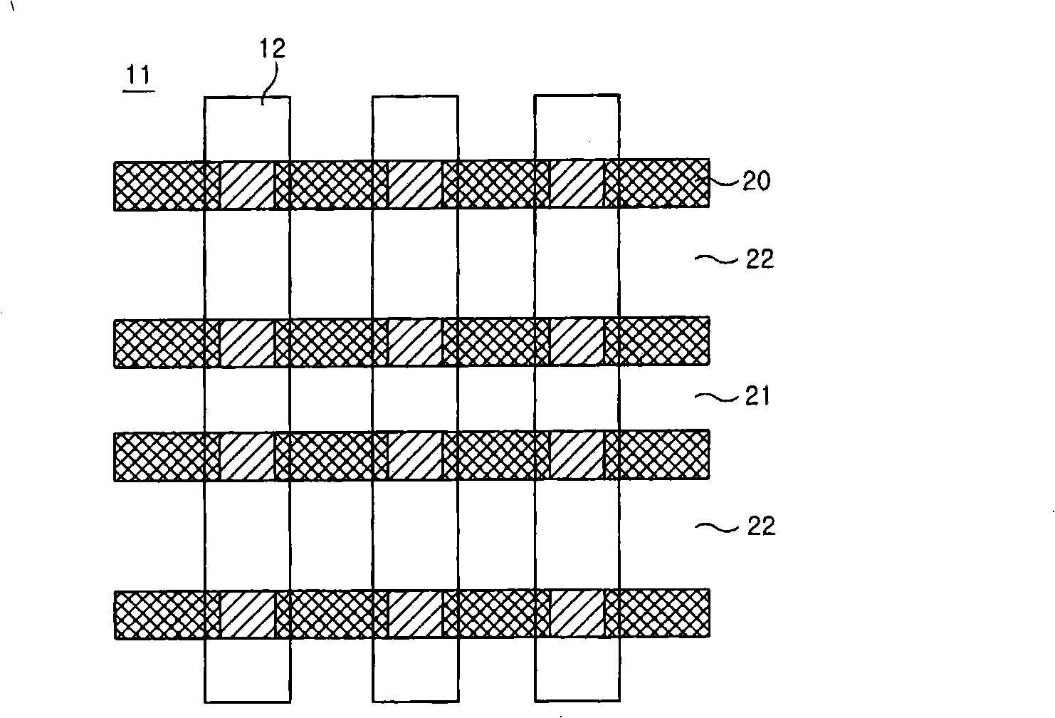
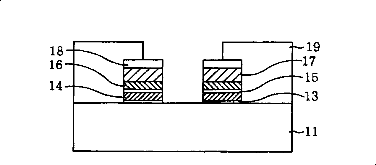
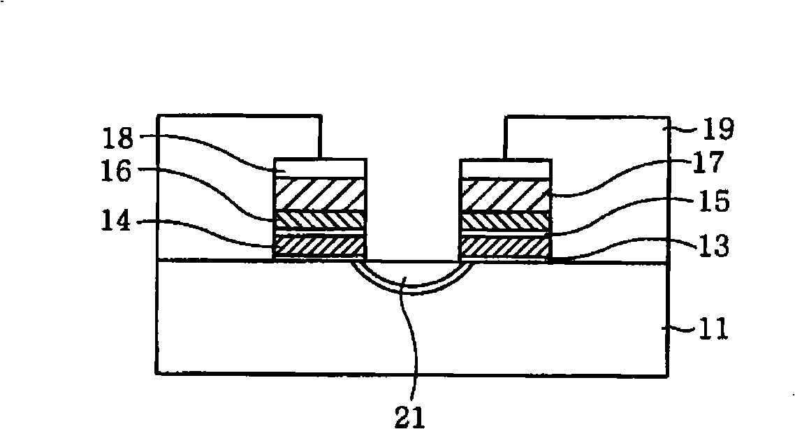
[0001] This application claims priority under 35 U.S.C §119 to Korean Patent Application No. 10-2007-0050823 (filed May 25, 2007), the entire contents of which are hereby incorporated by reference. Background technique [0002] A self-aligned source process may generally be used to form source lines of semiconductor memory devices. In the self-aligned source process, after the stacked gate structure is formed, the cell area excluding the common source part can be covered with a photosensitive film, the device isolation film of the source line part can be removed by etching, and ionization can be performed. implanted to form a common source line. [0003] as in the exemplary figure 1 and Figure 2A As illustrated in , device isolation film 12 may be formed on and / or at a device isolation region over semiconductor substrate 11 . A trench oxide film 13 and a first polysilicon film 14 may be sequentially formed on and / or over the entire structure, and then patterned by a photol...

Claims


Application Information

Patent Timeline
Patent Type & Authority Applications(China)
IPC IPC(8): H01L21/8247H01L21/768H01L21/336H01L21/28H01L27/115H01L23/532H01L29/788H01L29/43H10B12/00H10B69/00
CPCH01L27/115H01L21/28518H01L27/11521H10B69/00H10B41/30H01L21/28052
Inventor 高永善
Owner DONGBU HITEK CO LTD
Learn More