
Antenna switching system and related method

An antenna switching and antenna technology, applied in radio transmission systems, radio wave measurement systems, antennas, etc., can solve problems such as circuit saturation, achieve good signal reception, and reduce power consumption.

Inactive Publication Date: 2008-11-26
MEDIATEK INC
View PDF0 Cites 25 Cited by
  • Summary
  • Abstract
  • Description
  • Claims
  • Application Information

AI Technical Summary

Problems solved by technology

Because the energy of the interfering signal is usually much greater than the energy of the GPS navigation signal, if the active antenna 225 is continuously used to receive the GPS navigation signal, some circuits in the GPS receiving system 100 may be saturated

Method used


Image

  • Antenna switching system and related method
  • Antenna switching system and related method
  • Antenna switching system and related method

Examples


Embodiment Construction

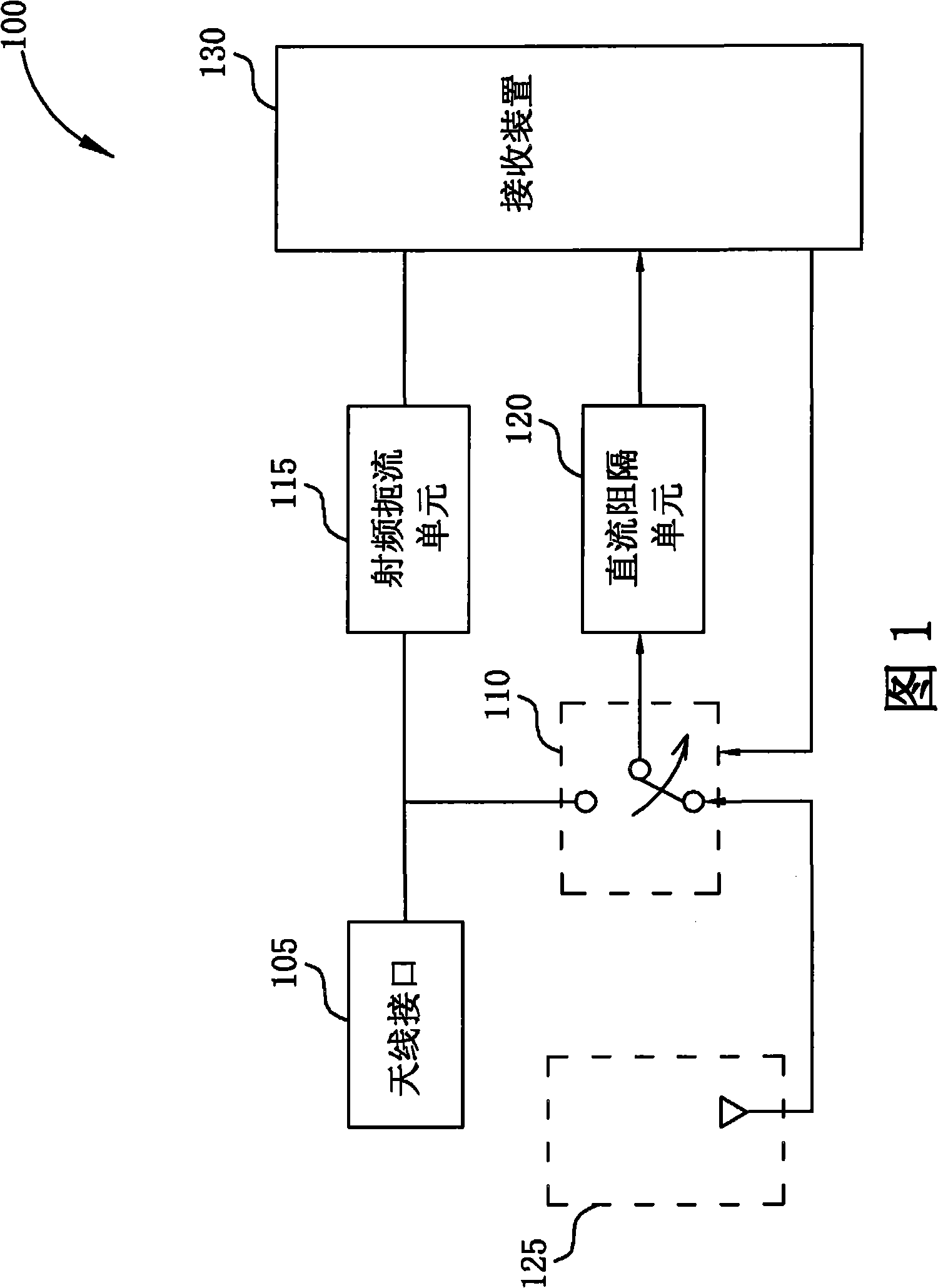
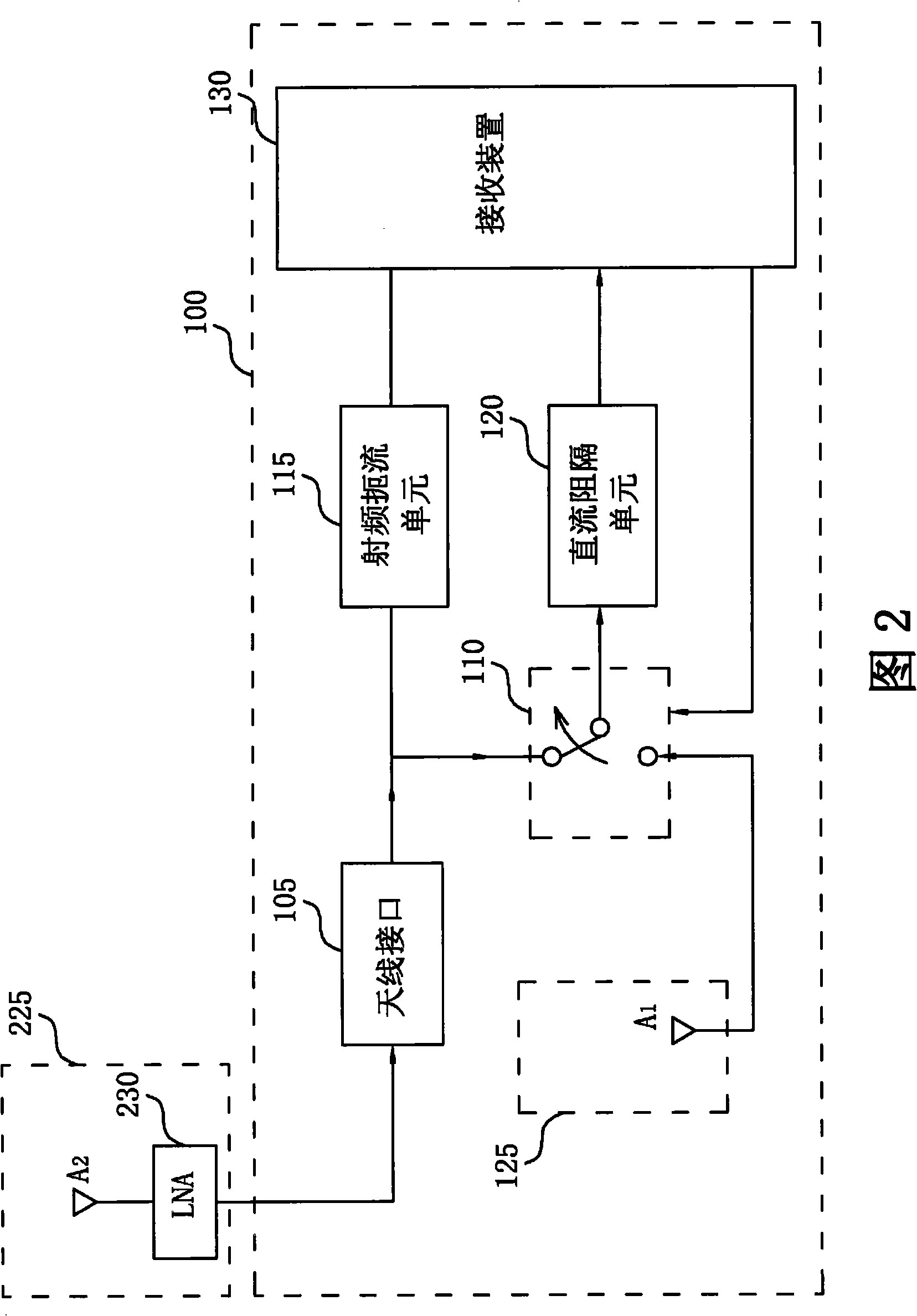
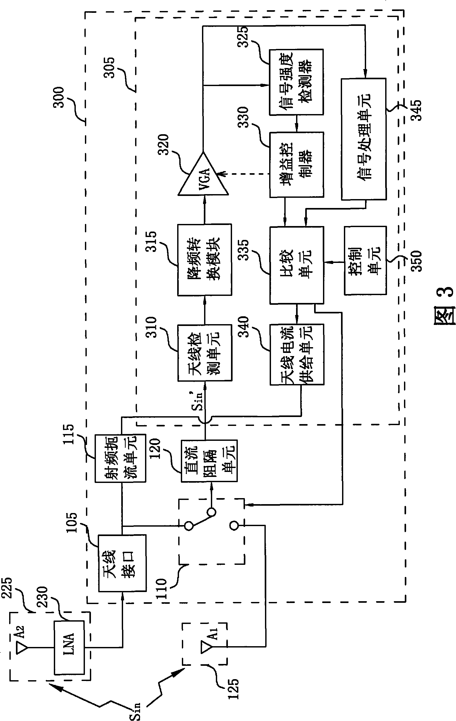
[0019] Please refer to Figure 3. FIG. 3 is a schematic diagram of an antenna switching system 300 according to an embodiment of the invention. In the following description, for ease of illustration, the antenna switching system 300 of this embodiment is based on the global positioning system (global positioning system, hereinafter referred to as GPS); however, the present invention can also be used in other systems that selectively use the first antenna Or an antenna switching system that receives signals with a second antenna with a gain different from that of the first antenna, for example: an antenna switching system based on the Beidou navigation system or the Galileo positioning system. Please note that the first antenna and the second antenna can be two active antennas with different gains, or two passive antennas with different gains, or one is an active antenna and the other is a passive antenna, these changes are all in the scope of the present invention within range...


PUM


Abstract

An antenna switching system for switching between a first antenna and a second antenna, where a gain of the first antenna is different from a gain of the second antenna, is disclosed. The antenna switching system includes an antenna switch unit and a switch control device. The antenna switch unit is selectively coupled to the first antenna or the second antenna. The switch control device is coupled to the antenna switch unit and utilized for controlling the antenna switch unit to switch between the first antenna and the second antenna according to at least a predetermined threshold value and an incoming wireless signal received from the antenna switch unit to achieve some purposes such as reducing power consumption and anti-jamming.

Description

technical field [0001] The present invention relates to a wireless receiving design, in particular to an antenna switching system and a related method for controlling an antenna switching unit to switch between a first antenna and a second antenna. Background technique [0002] Generally speaking, in the wireless receiving system, the antenna is an indispensable part. For a general wireless receiving system (for example: a wireless transceiver or a radio frequency receiver), the antenna has been integrated into the receiving system before leaving the factory. There is little chance that the user will add another antenna to the receiving system. However, in other wireless receiving systems, such as: Global Navigation Satellite System (Global Navigation Satellite System, hereinafter referred to as GNSS) receiving system, or mobile phones, an antenna interface (which is usually called a vehicle configuration interface) will be provided for The user inserts another antenna, wh...

Claims


Application Information

Patent Timeline
Patent Type & Authority Applications(China)
IPC IPC(8): H04B7/185H04B1/40
CPCH01Q21/28H01Q3/24G01S19/34H04B7/0814H04K3/226G01S19/21G01S19/36Y02D30/70
Inventor 欧阳正一
Owner MEDIATEK INC
Learn More