Cast-in-situ section steel concrete cavity building roof

A cavity floor and concrete technology, which is used in the on-site preparation of floor slabs and building components, formwork/template/work frame, etc. To improve the ability to resist top pressure and lateral pressure, maintain stability, and enhance rigidity

Inactive Publication Date: 2008-12-03
王本淼
View PDF2 Cites 17 Cited by
  • Summary
  • Abstract
  • Description
  • Claims
  • Application Information

AI Technical Summary

Problems solved by technology

However, the profiled steel plate must be placed on the upper flange of the profiled steel beam. The usual tensile reinforcement is constrained by the profiled steel web and can only be arranged on the upper flange of the profiled steel. The contact surface of the cast-in-place reinforced concrete on the profiled steel is small. , To prevent displacement, welding cylinder head bolts are required for positioning, especially the exposed parts of steel webs and upper and lower flanges need to be protected by fire-resistant coatings, the construction cost is high, and the sound insulation of the floor is poor
[0003] Publication number is that the patent of CN1310276A discloses a kind of, lay profiled steel plate on profile steel, make hollow floor again on profiled steel plate, this way makes the load-bearing capacity of floor cover big, but the floor cover its built up like this There are also protruding steel sections, and the top of the steel sections must be coated with fireproof materials. The addition of profiled steel plates increases the cost, and also increases the difficulty and expense of later decoration. This structure also indirectly increases the height of the entire building. , but the usable height has not increased, so the structure is not decorated and affects the appearance
[0004] The patent of Publication No. CN1766252A discloses a profiled steel web protruding from the profiled steel upper flange. The degree of bonding between the cover and the section steel, but this method makes the section steel into a movable connection, and its production and installation will take more time and cost
Moreover, existing products cannot be applied, and the lower flange of the section steel still protrudes from the lower flange surface of the floor

Method used


Image

  • Cast-in-situ section steel concrete cavity building roof
  • Cast-in-situ section steel concrete cavity building roof
  • Cast-in-situ section steel concrete cavity building roof

Examples


specific Embodiment approach 1

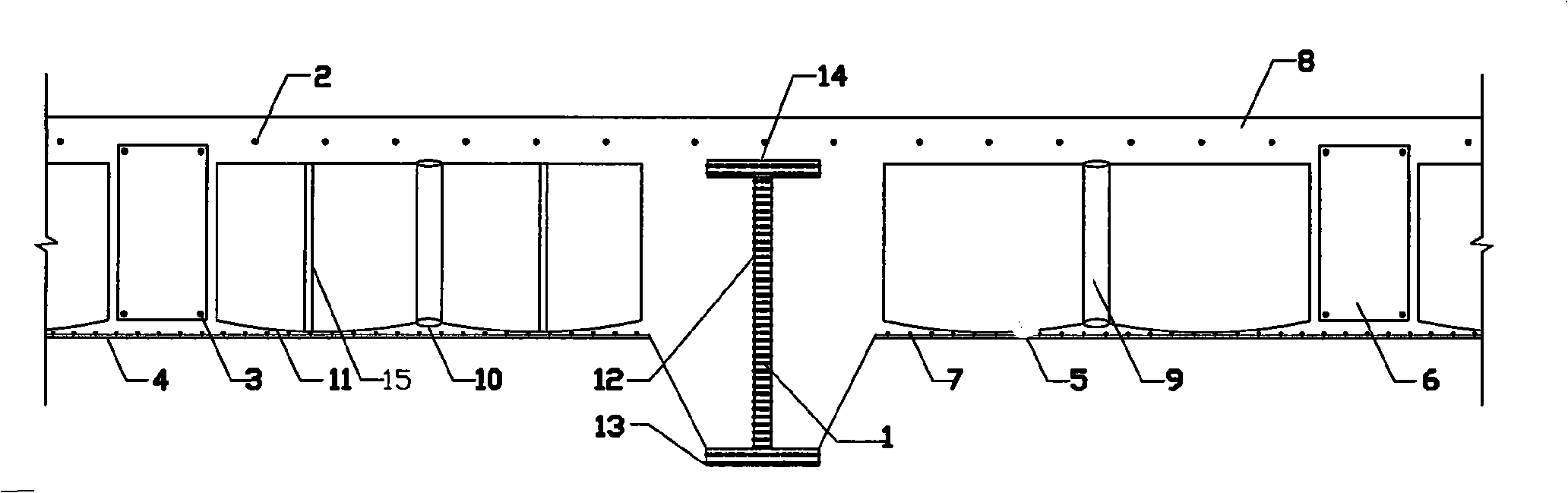
[0029] Specific implementation mode one, such as figure 1 As shown, this scheme is when the section steel 1 is higher than the situation of the floor: after the steel column frame of the building is built, when the floor is built, the floor formwork 4 is laid on the left and right sides of the main beam section steel 1, and then the floor formwork 4 is laid on the floor Lay a layer of steel wire mesh on the formwork 4, or lay glass fiber cloth or fiber cloth as a lining, and then place the rib beam 6 lower steel bar 3 arranged according to the design drawing, from the reserved hole 31 of the web 12 of the profile steel 1 The steel bars that are too long can be cut and then welded. The upper steel bar of the rib beam 6 passes through the upper part of the upper flange 14 of the profile steel 1. Finally, the rib beam 6 forms a vertical and horizontal grid with the size of a hollow body, and then the grid The hollow body is placed in the grid, and the hollow body bottom plate 11 ...

Embodiment approach 2

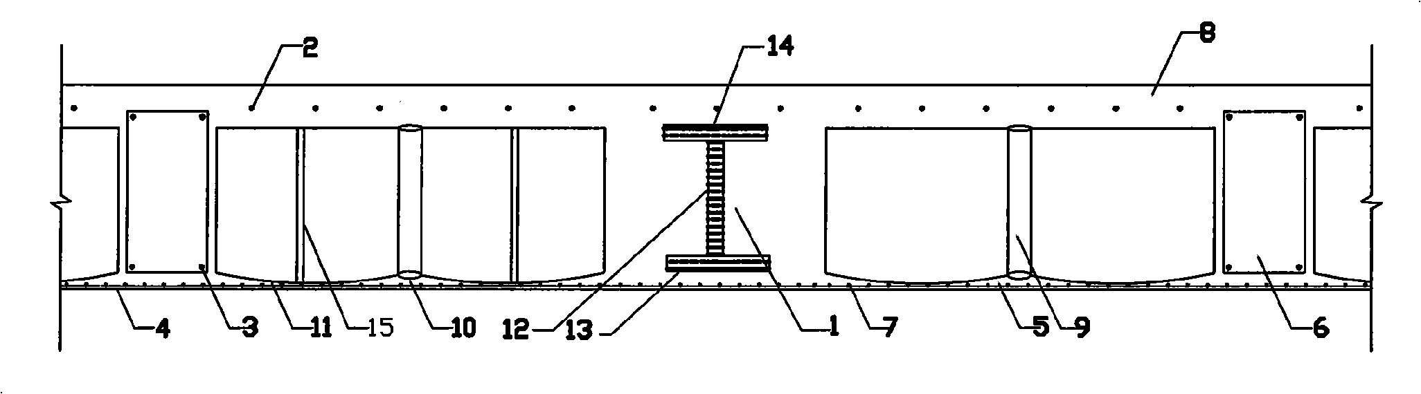
[0030] Implementation mode two: if figure 2 As shown, the main girder section steel of this scheme is lower than the lower flange plate of the floor. The main difference from the previous embodiment is that the floor template 4 is located at the bottom of the bottom flange 13 of the section steel 1 and the distance from the section steel 1 is 18 Within millimeters, the lining laid by the steel wire mesh is also located under the section steel 1, and the floor lower flange plate 5 formed by the arc height of the bottom surface of the hollow body is equal to the bottom surface of the section steel lower flange 13, and the finally poured floor forms the bottom surface Smooth "beamless" cast-in-place steel concrete cavity floor.


PUM


Abstract

The invention relates to a structure of a hollow floor system of cast-in-site steel-concrete in architectural engineering. The structure adopts the technical proposal that a special communicating hole for a common rib at the bottom part of a ribbon strip is manufactured in a web of section steel; the reinforcing steel bar at the bottom part of the ribbon strip penetrates through the communicating hole of the web of the section steel; the upper part penetrates through the upper flange of the section steel; a grid with the size of a crisscrossed prefabricated hollow body is formed; a hollowed hollow body is placed into the grid; and then concrete and mortar are poured into the hollow body, thereby the upper flange and the web of the section steel form into a whole with the entire floor system. By adopting the proposal, the reinforced concrete can be in close contact with the section steel, ans the bearing effect of the floor system is better. A plurality of raised arcs are formed on the bottom surface of the hollow body in the proposal, therefore, during the process of pouring the concrete and the mortar, the mortar can enter the bottom surface of the hollow body, the lower flange plate of the floor system forms a smooth surface after being solidified, and the problem that the secondary processing is still required to be performed to the bottom surface in the prior art can be overcome.

Description

technical field [0001] The invention relates to a building structure, in particular to a building construction with a cast-in-place concrete cavity floor covering containing section steel. Background technique [0002] At present, the construction of buildings on the building basically adopts cast-in-place reinforced concrete structure, steel structure, steel concrete structure, steel tube concrete structure, cast-in-place reinforced concrete hollow floor and cast-in-place reinforced concrete hollow floor, etc. In recent years, steel structures And the steel-concrete structural system is developing rapidly. The current method is mainly to use steel as the skeleton, and use profiled steel plates to replace part of the tensile structural steel bars and floor formwork. This method has better toughness and bearing capacity than reinforced concrete. However, the profiled steel plate must be placed on the upper flange of the profiled steel beam. The usual tensile reinforcement is ...

Claims


Application Information

Patent Timeline
Patent Type & Authority Applications(China)
IPC IPC(8): E04B5/36E04C5/01E04G15/06
Inventor 王本淼王海崴
Owner 王本淼
Why Eureka
Try Eureka