Engine with double-push bar tappet rod and stand-alone interstice regulator, and air valve mechanism thereof

A technology for lash adjusters and valve trains, applied in the direction of machines/engines, engine components, mechanical equipment, etc., which can solve problems such as expensive, cost-effective, and high wear rates

Inactive Publication Date: 2008-12-03
FORD GLOBAL TECH LLC
View PDF0 Cites 10 Cited by
  • Summary
  • Abstract
  • Description
  • Claims
  • Application Information

AI Technical Summary

Problems solved by technology

A bridged valve train is a cost effective design that can achieve acceptable performance for many applications, although the operation of the two bridged valves is not precisely synchronized because the forces applied to the bridge may not be perfectly balanced between the valves Balanced, valves may have slightly different spring forces and valve assemblies may experience slightly different wear
This can cause one valve to open later and/or when the valve closes, one valve will

Method used


Image

  • Engine with double-push bar tappet rod and stand-alone interstice regulator, and air valve mechanism thereof
  • Engine with double-push bar tappet rod and stand-alone interstice regulator, and air valve mechanism thereof
  • Engine with double-push bar tappet rod and stand-alone interstice regulator, and air valve mechanism thereof

Examples


Embodiment Construction

[0014] Those skilled in the art will appreciate that the various features of the invention shown and described with reference to any one of the drawings may be combined with characteristics shown in one or more other drawings to produce Embodiments of the invention are described. The combinations of features shown provide typical embodiments for typical applications. However, various combinations and modifications of the features consistent with the teachings of the present invention may be required for particular applications or implementations.

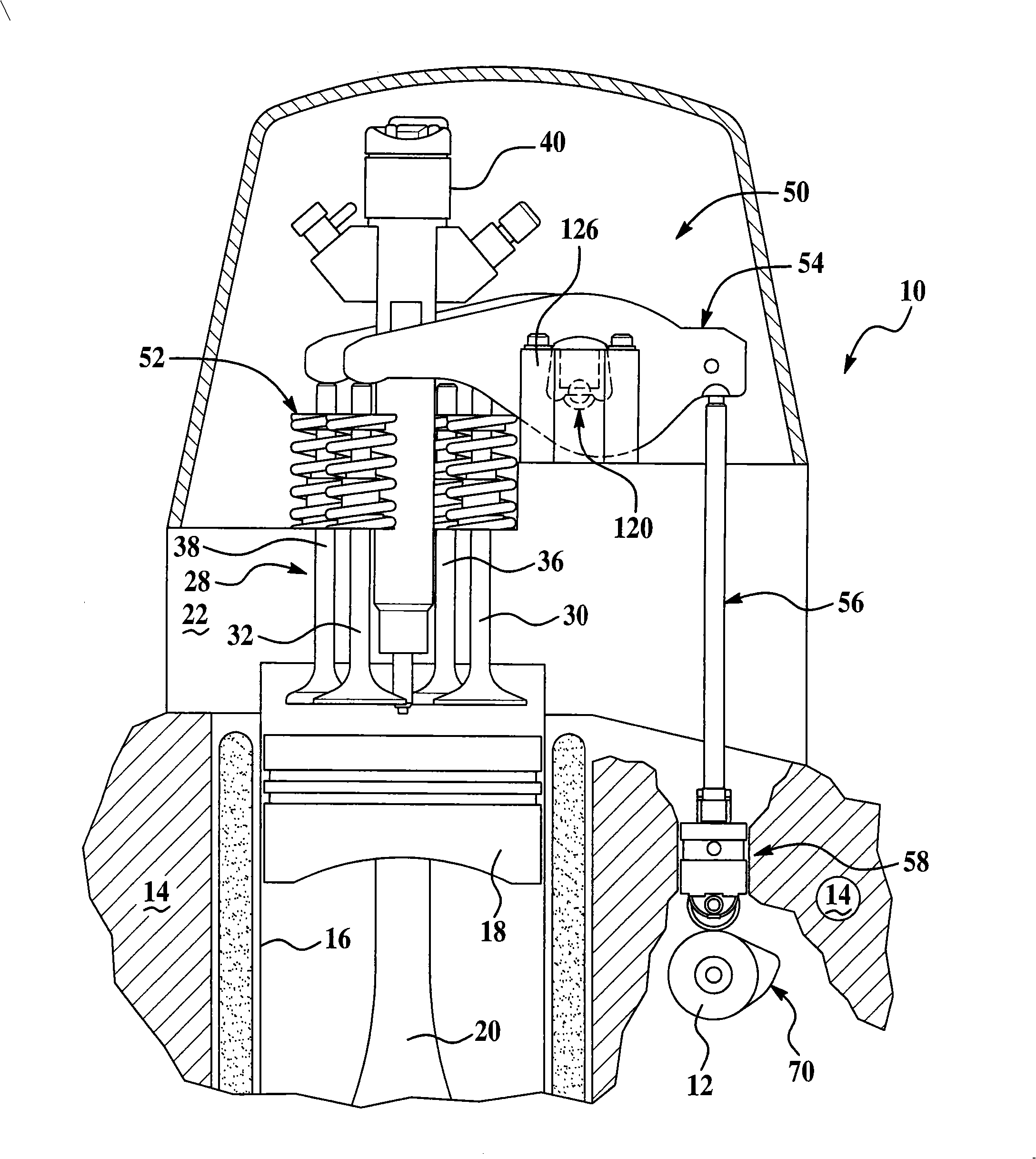
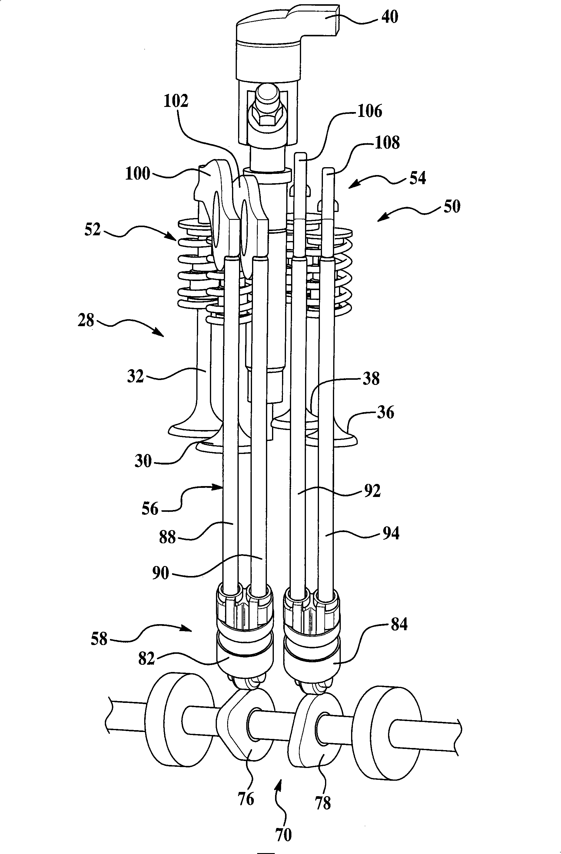
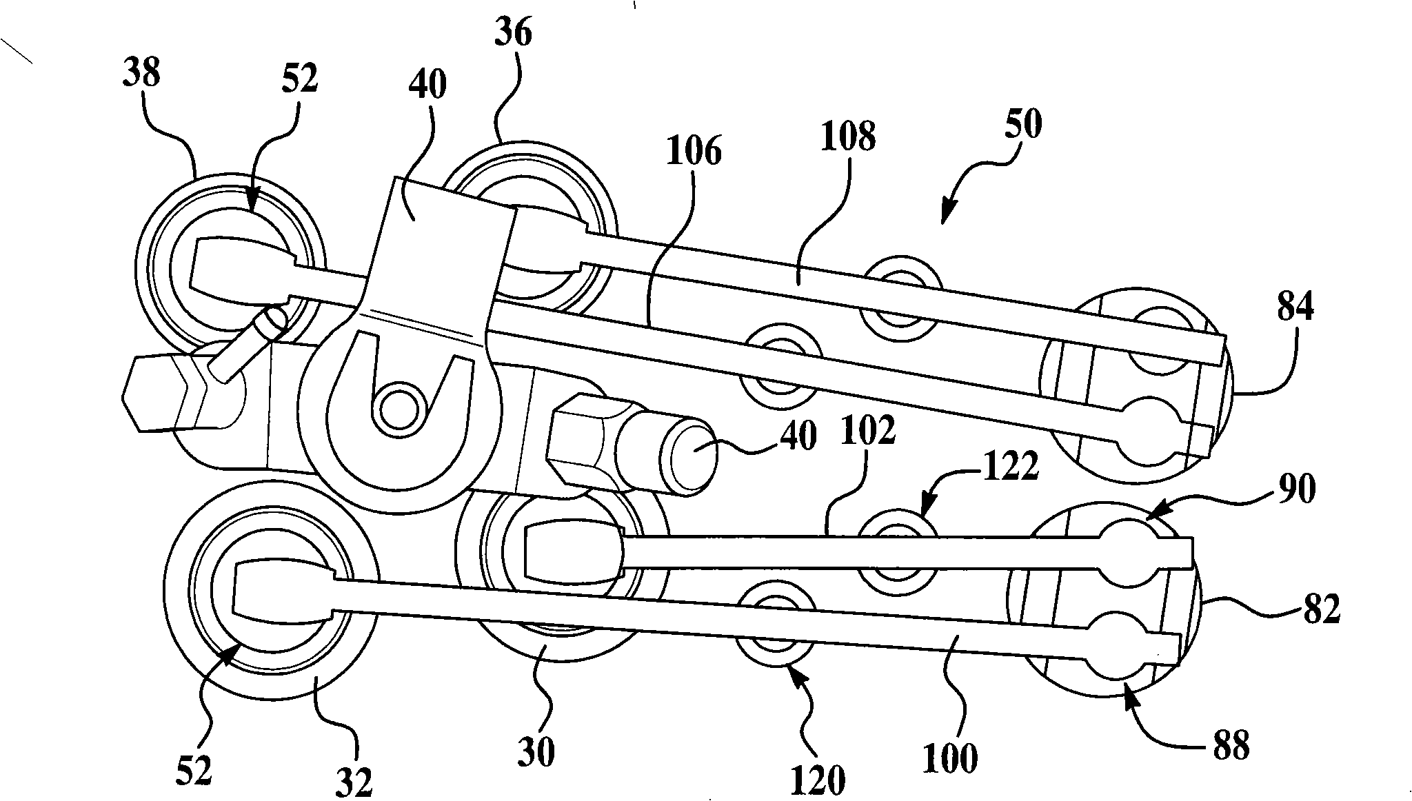
[0015] Figure 1-3 Operation of an internal combustion engine and valve train according to an exemplary embodiment of the present invention is shown. The multi-cylinder internal combustion engine 10 is generally of conventional design except for various valvetrain components as described herein. Accordingly, various conventional features associated with the engine and valvetrain are not particularly shown or described. Those ski...


PUM


Abstract

A multi-cylinder internal combustion engine with a camshaft-driven valve mechanism comprises at least two inlet valves and/or exhaust valves and a valve mechanism including a camshaft arranged in the cylinder of the engine, wherein the pair of valves are operated by the cam crown of a common camshaft and a cam driven part. The valve mechanism may include mechanical or hydraulic clearance adjusters capable of being operated independently. The cam driven part contacts with the cam crown of the common camshaft and at least two push rods, each push rod includes associated single-planar rocking arm, and the rocking arm is connected with a pivot arranged on a cylinder cover for driving the at least two valves.

Description

technical field [0001] The present invention relates to a multi-cylinder internal combustion engine having intake / exhaust valves and associated valve trains operated by a camshaft positioned in the engine block. Background technique [0002] Existing internal combustion engines use a camshaft-actuated valvetrain to operate the intake and exhaust valves that control the exchange of gases in the combustion chambers formed between the engine's cylinder block and cylinder head. Engines are generally classified by the position of the camshaft relative to the valves, with overhead cam valvetrains being driven by the camshafts above the valves in the cylinder head, and pushrod valvetrains or "block-in-block cam" valvetrains having a camshaft located in the engine block The camshaft in the engine and the valves operated by pushrods and rocker arms. [0003] Existing pushrod engines with four valves per cylinder include two intake valves and two exhaust valves per cylinder. Each pa...

Claims


Application Information

Patent Timeline
IPC IPC(8): F01L1/18F01L1/255
Inventor 马修·B·迪格斯沃利·比伯罗伯特·因尼斯
Owner FORD GLOBAL TECH LLC
Why Eureka
Try Eureka