
Wall type arranged horizontal rich-lean direct current combustion device

A combustion device and horizontal technology, applied in the field of coal-fired boilers, can solve problems such as slagging and high-temperature corrosion, and different gas supply conditions on both sides of the pulverized coal flow, so as to improve gas supply conditions and reduce water wall slagging and high-temperature corrosion , good effect

Active Publication Date: 2010-06-09
HARBIN INST OF TECH
View PDF1 Cites 1 Cited by
  • Summary
  • Abstract
  • Description
  • Claims
  • Application Information

AI Technical Summary

Problems solved by technology

[0005] The purpose of the present invention is to provide a wall-type horizontal thick-lean direct-flow combustion device to solve the problem of tangential circle arrangement at four corners of the direct-flow burner. The air supply conditions on both sides of the pulverized coal flow are different, and deflection is prone to occur, causing slagging and high-temperature corrosion problems.

Method used


Image

  • Wall type arranged horizontal rich-lean direct current combustion device
  • Wall type arranged horizontal rich-lean direct current combustion device
  • Wall type arranged horizontal rich-lean direct current combustion device

Examples


specific Embodiment approach 1

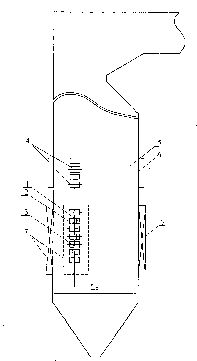
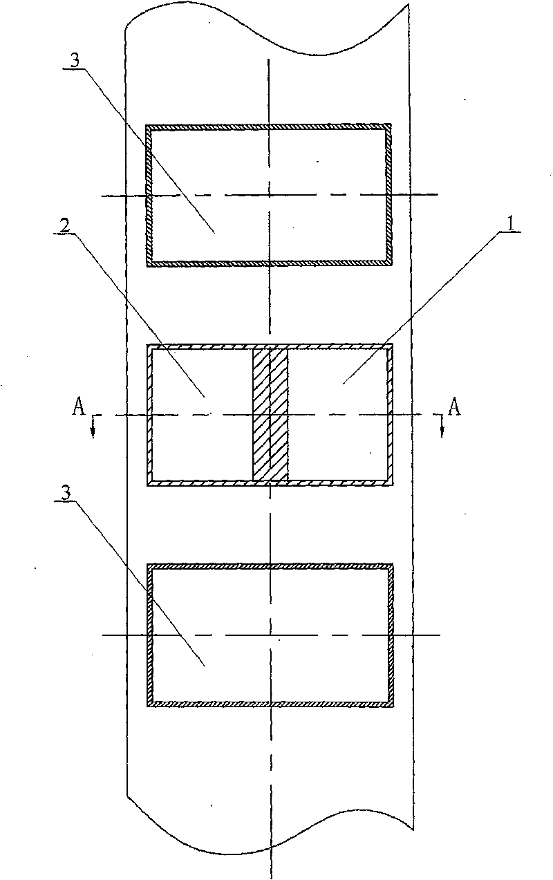
[0009] Specific implementation mode 1: Combination Figure 1~Figure 8 To illustrate this embodiment, this embodiment consists of a furnace 5, a plurality of concentrated primary air nozzles 1, a plurality of weak primary air nozzles 2, a plurality of secondary air nozzles 3, and four sets of burn-out air nozzles 4. The furnace 5 consists of Surrounded by water-cooled walls 6 on all sides, the four-sided water-cooled walls 6 of the furnace 5 are respectively provided with a plurality of concentrated primary air nozzles 1, a plurality of weak primary air nozzles 2 and a plurality of secondary air nozzles 3, each of the water walls The multiple dense primary air nozzles 1, multiple weak primary air nozzles 2 and multiple secondary air nozzles 3 set on 6 are combined to form a set of burners 7. The four sets of burners 7 are respectively arranged on the same horizontal surface, so The secondary air nozzles 3 in each group of burners 7 are alternately arranged up and down with the r...

specific Embodiment approach 2

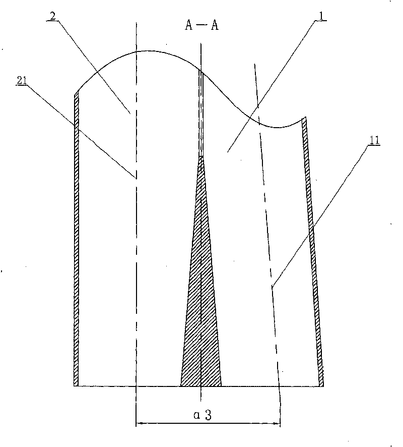
[0012] Specific implementation manner two: combination figure 1 , Figure 4 with Figure 8 To describe this embodiment, the distance between the center line 31 of the secondary air nozzle 3 provided on each water wall 6 and the intersection point on the water wall 6 where it is located is L from the corner of the nearest furnace 5 1 , 1 / 5Lk≤L 1 ≤1 / 2Lk; or 1 / 5Ls≤L 1 ≤1 / 2Ls, the Lk is the width of the furnace, and the Ls is the depth of the furnace. The angle between the center line 31 of the secondary air nozzle 3 in this embodiment and the water wall 6 on the fire side is 54°≤α 1 ≤127°, the angle between the center line 21 of the light primary air nozzle 2 and the water wall 6 on the fire side is 54°≤α 2 ≤127°, the angle between the centerline 11 of the concentrated primary air nozzle 1 and the centerline 21 of the weak primary air nozzle 2 is 0°≤α 3 ≤15°, the concentrated primary wind jet is arranged on the fire side, and the light primary wind jet is arranged on the back fire si...

specific Embodiment approach 3

[0013] Specific implementation mode three: combination Figure 5 To illustrate the present embodiment, the over-burned air nozzle 4 of this embodiment is provided on each corner of the furnace 5. When viewed from above the furnace 5, the center line 41 of the over-fired air nozzle 4 is opposite to it in a clockwise direction. The angle between the adjacent water wall 6 is 20°≤α 4 ≤70°. With this arrangement, the layout of the over-fired air is easy to realize, and the furnace full of the combustion air flow is better. Other components and connection relationships are the same as in the second embodiment.


PUM


Abstract

A wall-mount horizontal bias direct-flow combustion device relates to a horizontal bias direct-flow combustion device. The invention solves the problems of the prior direct-flow combustor, such as four-corner tangential arrangement, different air supply conditions of coal flows on two sides, high risk of slag deposition due to declination and corrosion at high temperature. First dense / dilute air jet ports and a second air jet port (3) are formed on the water-cooled wall (6) of a furnace cavity (5) and combined to form a group of combustors (7). The central line (31) of the second air jet portand the central line (21) of the first dilute air jet port (2) are positioned in the fire-facing side direction, and have the included angles of alpha 1 and alpha 2 with relative to the water-cooled wall (6), on which the jet ports are positioned. The included angle between the central line (11) of the first dense air jet port and the central line (21) of the first dilute air jet port (2) is alpha3. After-burn air jet ports (4) are arranged on the water-cooled wall (6) or at each corner of the furnace cavity (5). The After-burn air jet ports (4) are positioned above the combustors (7). The wall-mount horizontal bias direct-flow combustion device realizes reasonable combination of coal particles and air, prevents the deflection of coal flow, and ensures stable combustion, low load and lowNOx discharge of boilers.

Description

Technical field [0001] The invention relates to a horizontal thick and thin direct current combustion device, in particular to the technical field of coal-fired boilers. Background technique [0002] The four-corner tangential arrangement of the direct current burner and the front wall or the opposite arrangement of the swirl burner are one of the two most widely used pulverized coal combustion methods in the world. The four-corner tangentially arranged combustion method is to inject pulverized coal (primary air) and secondary air into the furnace in a manner tangent to an imaginary tangent circle at the four corners of the furnace and the center of the furnace to achieve tangential combustion of the pulverized coal. The four-corner flames formed by the four-corner tangential direct-flow combustion technology can support each other, and the flue gas generated by combustion rotates and rises in the furnace. It has the characteristics of long flame stroke, good mixing in the furnac...

Claims


Application Information

Patent Timeline
Patent Type & Authority Patents(China)
IPC IPC(8): F23C5/08F23C7/00
CPCF23C7/02F23C5/10F23C5/32
Inventor 吴少华孙绍增刘辉秦明秦裕琨
Owner HARBIN INST OF TECH
Learn More