Method for manufacturing front fork of compound material

A production method and bicycle technology, which are applied to bicycle frames, bicycle accessories, steering mechanisms, etc., can solve the problems of increased processing difficulty, high failure rate, and damage to the continuity of composite fibers, so as to simplify the process and solve the problem of qualified rate. , Improve the effect of support strength

Active Publication Date: 2008-12-10
XIAMEN KEENTECH COMPOSITE TECH CO LTD
View PDF0 Cites 4 Cited by
  • Summary
  • Abstract
  • Description
  • Claims
  • Application Information

AI Technical Summary

Problems solved by technology

[0004] 1. Because the three-pipe connection of the front fork needs to be equipped with a brake, the brake hole 3' must be installed, and the three air pipes of the front fork are set in such a way that the three pipes are formed into an integrated structure. The brake hole 3' The secondary drilling process must be used for processing, which makes the processing process cumbersome
[0005] 2. Furthermore, when the brake hole 3' is drilled, the coaxiality of the hole must be ensured to ensure the function of the brake, and the thickness of the three-tube joint of the pre-processed composite front fork tube is thicker to ensure that the brake hole The coaxiality makes processing relatively more difficult, so the failure rate is higher
[0006] 3. Because the secondary processing of the brake hole 3' will destroy the continuity of the composite fiber, it will inevitably affect the support strength of the front fork tube
[0007] 4. The winding formation of an air duct of vertical pipe 1' is also the reason for its insufficient support strength

Method used


Image

  • Method for manufacturing front fork of compound material
  • Method for manufacturing front fork of compound material

Examples


Embodiment Construction

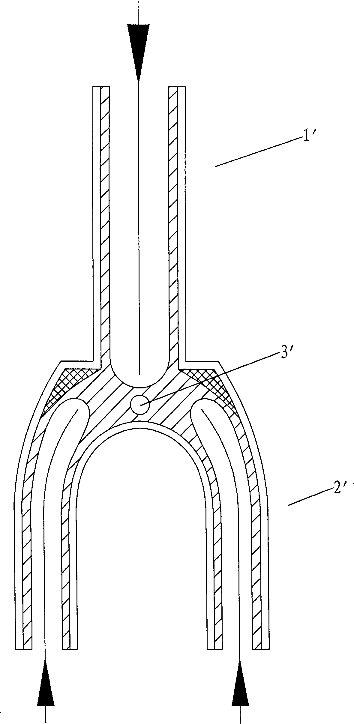
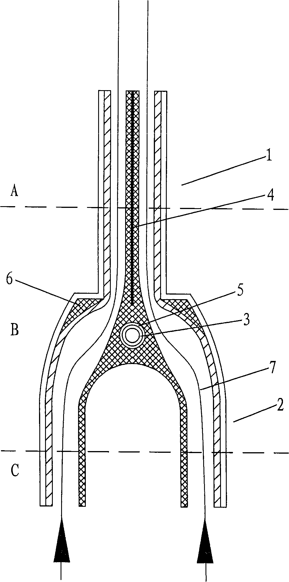
[0022] like figure 2 As shown, the manufacturing method of the composite bicycle front fork of the present invention is mainly that the front fork is formed by changing the traditional three-tube independent winding method of three bobbins into two bobbins.

[0023] As shown in the matching figure, firstly, the composite material is wound into two bobbins respectively, the lower parts of the two bobbins are separated to form two fork tubes 2 of the front fork, and the upper parts of the two bobbins are brought together to form a front fork. Form the standpipe 1 of the front fork, and add a hard metal sheet 4 between the abutment of the two bobbins. Increase the support strength of the standpipe 1; insert a brake hole inner core 5 at the position of the brake hole 3 between the two yarn bobbins, and the brake hole inner core 5 has a brake hole to place the brake; The shape of the front fork is filled with yarn at the joint position; finally, the bobbin is placed in the formin...


PUM


Abstract

A manufacturing method for a front fork of a composite bicycle is characterized in that a vertical pipe and two breeches pipes are pre-shaped by two wind pipes; the steps include: two bobbins are respectively rolled by composite materials; the wind pipes are arranged in the two bobbins; the lower parts of the two bobbins are separated to form two breeches pipes; while the upper parts of the two bobbins are combined together to form the vertical pipe; then the inner core of a brake hole provided with a through hole is arranged in the position of a brake between the two bobbins; then yarn complementing is carried out at the connecting location of the two bobbins according to the shape of the front fork; finally the bobbins are arranged in a die for being heated, solidified and shaped. The wind pipes are directly communicated with the vertical pipe by the breeches pipes; the wind pipes can correct the consequent property of the fiber of the composite yarn and can ensure the supporting intensity of the front breeches pipe; the vertical pipe of the front breeches pipe is combined together and shaped by two bobbins; the combining location of the two bobbins naturally forms one reinforcing rib in the vertical pipe; the arrangement of the inner core of the brake hole is to integrally shape the penetrating hole of the brake on the front breeches pipe when the front breeches pipe is shaped without the working procedure of secondary drilling, thus the intensity of the front breeches pipe is not affected under the premise of ensuring the coax of the penetrating hole.

Description

technical field [0001] The invention relates to a manufacturing method of a polymer composite material pipe fitting, in particular to a manufacturing method of a composite bicycle front fork. Background technique [0002] In traditional bicycles, the entire vehicle frame is made of metal pipe fittings, but the bicycle with this welded metal structure has a heavy body and poor fatigue resistance. Therefore, in order to reduce the weight of the vehicle body and increase its fatigue resistance, the entire vehicle frame is made of light-weight, high-strength polymer composite carbon fiber material. [0003] When the existing composite bicycle front fork structure is formed, the figure 1 As shown, the vertical pipe 1' is independent winding, and at the same time, the two fork pipes 2' are also independently winding, and the yarn is mended at the joint of the three pipes, and then the air pipes are respectively installed in the three yarn pipes, and placed in the front In the fo...

Claims


Application Information

Patent Timeline
Patent Type & Authority Applications(China)
IPC IPC(8): B62K21/02B62K19/02
Inventor 陈敬达
Owner XIAMEN KEENTECH COMPOSITE TECH CO LTD
Why Eureka
Try Eureka