
Signal-number conversion method of rotating transformer

A resolver and digital conversion technology, which is applied in the field of sensor measurement, can solve the problems of unfavorable industrial measurement and control fields, the cost of measurement systems, the increase of volume, and the reduction of product cost performance. The effect of small volume

Active Publication Date: 2008-12-10
连云港杰瑞电子有限公司
View PDF0 Cites 18 Cited by
  • Summary
  • Abstract
  • Description
  • Claims
  • Application Information

AI Technical Summary

Problems solved by technology

At present, there are dedicated R / D converters that can realize analog / digital conversion and angle calculation functions, but the cost is high, and it can only complete single-channel, single-frequency resolver signal-to-digital conversion. When multiple channels need to be completed at the same time , Multi-frequency resolver signal-to-digital conversion, using this method will increase the cost and volume of the entire measurement system with the increase in the number of channels and signal frequency types, which is not conducive to the promotion and use of industrial measurement and control fields , reducing the cost performance of the product

Method used


Image

  • Signal-number conversion method of rotating transformer
  • Signal-number conversion method of rotating transformer
  • Signal-number conversion method of rotating transformer

Examples


Embodiment 1

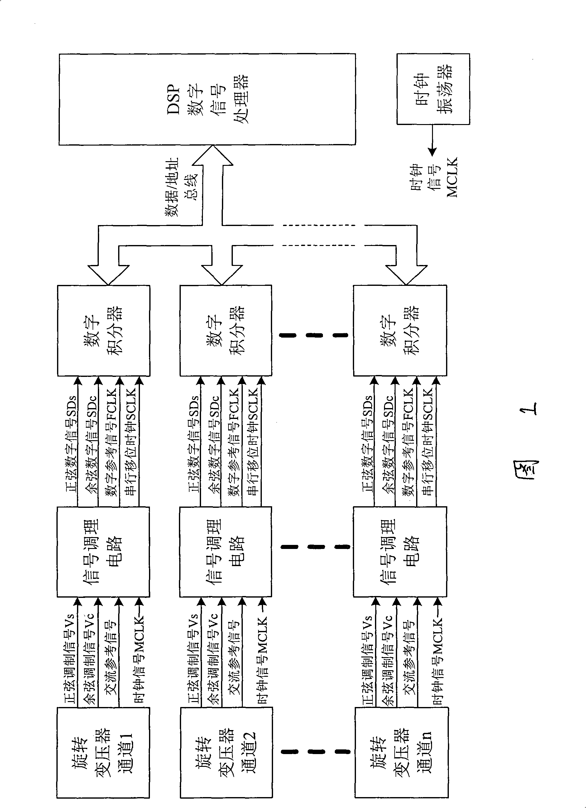
[0024] Example 1. Refer to Figure 1-3. A resolver signal-to-digital conversion method, which simultaneously digitizes the resolver signals of several channels, and then converts the sine and cosine modulation signals Vs and Vc output by the resolver through the DSP digital signal processor solution method into a binary digital angle signal;

[0025] It consists of signal conditioning circuit, digital integrator, clock oscillator and DSP digital signal processor;

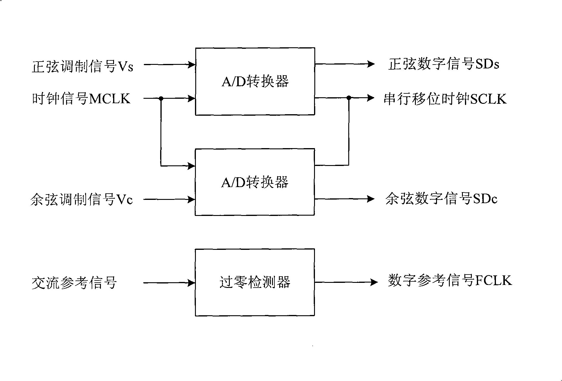
[0026] Each resolver channel is connected with a signal conditioning circuit, each signal conditioning circuit includes two A / D converters and a zero-crossing detector, and the two A / D converters respectively convert the sine and cosine signals output by a resolver channel The modulation signals Vs, Vc are converted into serial sine and cosine digital signals SDs, SDc, and a serial shift clock SCLK is output at the same time; the zero-crossing detector converts the channel's AC reference signal EoSinωt into a digit...

Embodiment 2

[0030] Example 2. In the resolver signal-to-digital conversion method described in Embodiment 1, the number of resolver channels is 2; the frequency of the resolver is 50-5000 Hz.

Embodiment 3

[0031] Example 3. In the resolver signal-to-digital conversion method described in Embodiment 1, the number of resolver channels is 12; the frequency of the resolver is 50-5000 Hz.


PUM

PropertyMeasurementUnit
Frequencyaaaaaaaaaa

Abstract

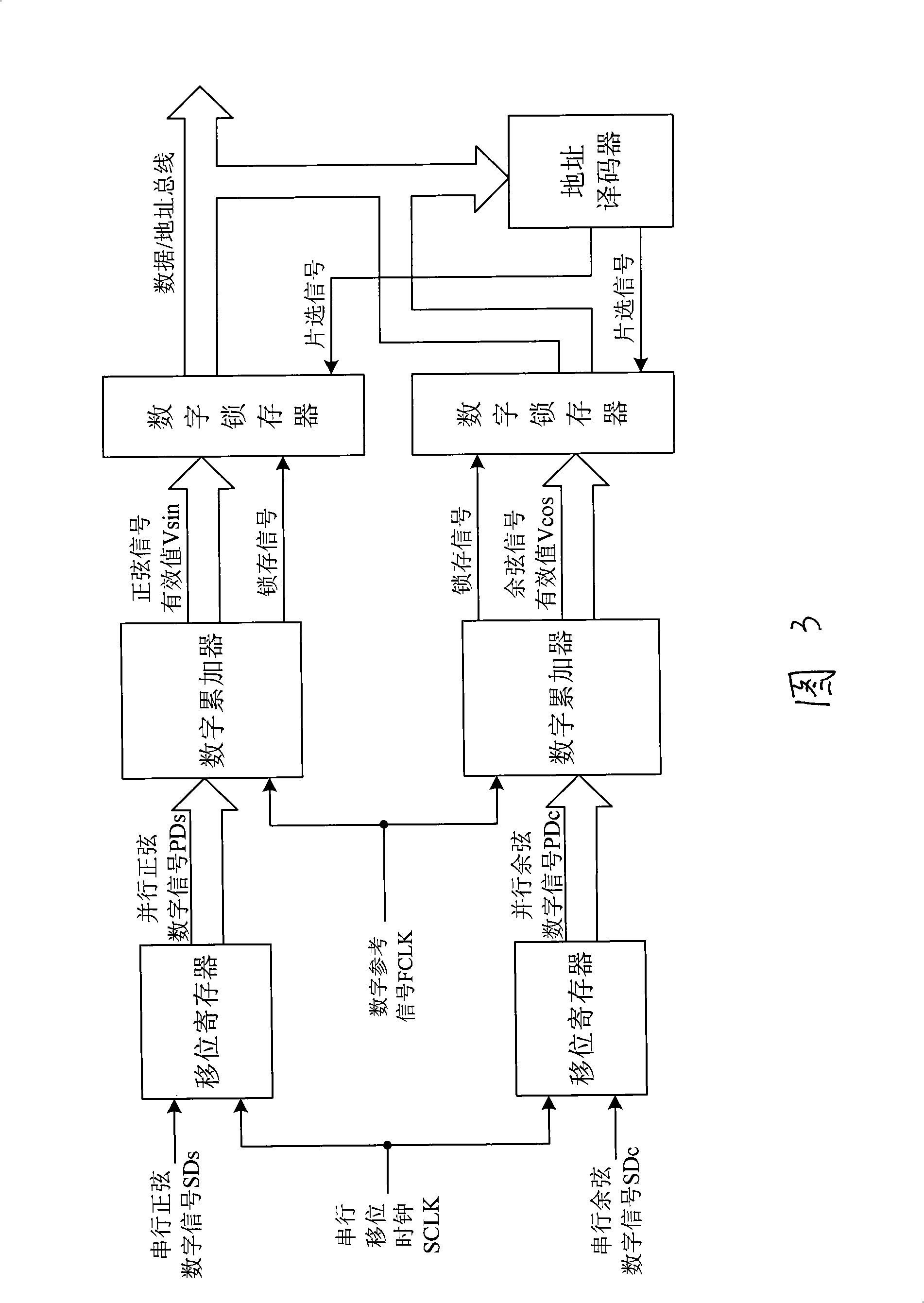
The invention relates to a signal-digit conversion method for a rotating transformer which is characterized by simultaneously carrying out digitle processing on the signals of the rotating transformers of a plurality of channels and converting a sine modulation signal Vs and a cosine modulation signal Vc outputted by the rotating transformer into a binary digit angle signals by the resolving method of a DSP digital signal processer. The invention consists of signal conditioning circuits, digital integrators, a clock oscillator and the DSP digital signal processer. Each rotating transformer channel is connected with one signal conditioning circuit; each signal conditioning circuit comprises two A / D convertors and a zero-crossing detector; each signal conditioning circuit is connected with one digital integrator; each digital integrator consists of two shift registers, two digital accumulators, two flip-latches and an address encoder. The measuring signal channel qualities of the conversion technology of the invention are more; the signal frequency range is broad; the digital angles are resolved by software, thus reducing the hardware cost, reducing the size and having a high cost performance.

Description

technical field [0001] The invention belongs to the technical field of sensor measurement, in particular to a resolver signal-to-digital conversion method. Background technique [0002] A resolver is an angle sensor whose output signal voltage changes with the rotor angle, and it is mainly used for coordinate transformation, trigonometric calculation and angle data transmission. When the reference winding is excited by an AC voltage of a certain frequency, the output voltages Vs and Vc of the sine and cosine windings have a sine and cosine function relationship with the rotation angle θ of the rotor, and the relationship is as follows: [0003] Vs=KEoSinωtSinθ [0004] Vc=KEoSinωtCosθ [0005] Among them, EoSinωt is the exchange reference signal, K is a constant. [0006] As a shaft angular displacement measuring element, the resolver has high precision, simple structure, and strong anti-interference ability. It is mainly used in occasions where the environment is harsh a...

Claims


Application Information

Patent Timeline
IPC IPC(8): G01D5/14
Inventor 程蜀炜夏伟李云飞寇志强杜雪珍
Owner 连云港杰瑞电子有限公司
Learn More