Magnetorheological finishing device for high-steepness optical part

A technology of magnetorheological polishing and optical parts, applied in the field of magnetorheological polishing, can solve the difficult problem that cannot be solved in the processing of high-steep optical parts, the curvature radius of high-steep parts changes drastically, and is not suitable for the processing of high-steep optical parts and other problems, to achieve the effect of wide application, simple and compact structure, and wide range

Inactive Publication Date: 2008-12-17
NAT UNIV OF DEFENSE TECH
View PDF2 Cites 21 Cited by
  • Summary
  • Abstract
  • Description
  • Claims
  • Application Information

AI Technical Summary

Problems solved by technology

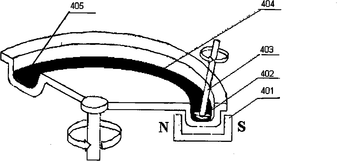
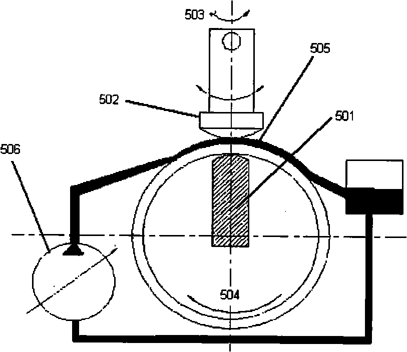
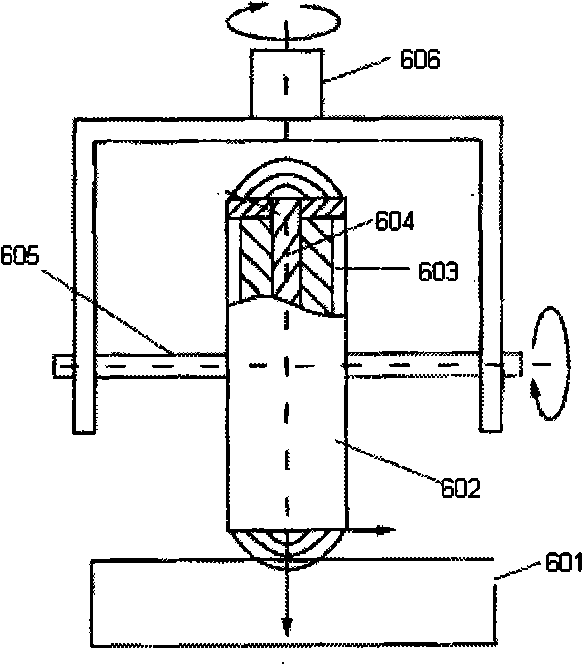
like figure 1 , 2 , 3 are schematic diagrams of some magnetorheological polishing devices established by existing research institutes in China. Harbin Institute of Technology has successively adopted figure 1 and figure 2 In the processing method shown, since the magnetorheological polishing spots formed in this patent are relatively large, when the curvature radius of the high-steep parts changes, the removal model also changes accordingly, and it is difficult to achieve magnetorheological deterministic polishing. It is not suitable for the processing of high-steep parts; Chinese patent number: 03153996.3, invention name: electromagnetic magnetorheological polishing head, which is developed by Tsinghua University such as image 3 The orbital and self-rotating polishing wheel device shown
Because in this device, the polishing wheel rotates and revolves at the same time, thus forming a large Gaussian shape removal function, the radius of curvature of the high-steepness

Method used


Image

  • Magnetorheological finishing device for high-steepness optical part
  • Magnetorheological finishing device for high-steepness optical part
  • Magnetorheological finishing device for high-steepness optical part

Examples


Embodiment Construction

[0063] The present invention will be described in further detail below in conjunction with the accompanying drawings and specific embodiments.

[0064] see Figure 4 As shown, the present invention is used for the magneto-rheological polishing device of high-steep optical parts, which includes a machine tool 1, a magneto-rheological polishing device 2 and a control system connected to each of the above components respectively. The bed 101 of the machine tool 1 is in the shape of "L" ” shape, which includes a horizontal base and a vertical base. The X-axis linear motion mechanism 102 and the Y-axis linear motion mechanism 103 are arranged on the horizontal base in a “cross” shape, and the X-axis linear motion mechanism 102 is fixed on the Y axis. On the slider of the Z-axis linear motion mechanism 103, the Z-axis linear motion mechanism 104 is arranged on a vertical base. On the block, the B-axis rotary table 106 used to install the workpiece fixture 109 is fixed on the slider...


PUM

PropertyMeasurementUnit
Diameteraaaaaaaaaa

Abstract

The invention relates to a magnetic rheological polishing device used in an optical part with high gradient, comprising a machine tool, a magnetic rheological polishing device and a control system which is connected with the above components. The machine tool comprises a horizontal base seat and a vertical base seat, an X axial linear motion mechanism and a Y axial linear motion mechanism are arranged on the horizontal base seat in a cross shape, the X axial linear motion mechanism is fixed on a slider of the Y axial linear motion mechanism, a Z axial linear motion mechanism is arranged on the vertical base seat, a C axial rotary worktable used for arranging the magnetic rheological polishing device is arranged on a slider of the X axial linear motion mechanism, a B axial rotary worktable used for arranging a work piece fixture is arranged on a slider of the Z axial linear motion mechanism, an A axial rotary worktable used for driving the work piece to be processed is arranged at the tail end of the work piece fixture, and the magnetic rheological polishing device is horizontally opposite to the work piece to be processed. The device of the invention has the advantages of simple and compact structure, low cost and easy control, and can realize the processing of the optical part with the high gradient.

Description

technical field [0001] The invention mainly relates to the technical field of magnetorheological polishing, in particular to a magnetorheological polishing device for high-steep optical parts. Background technique [0002] Deterministic polishing of high-steep optical parts is a key technical problem in the field of optical parts processing. High-steep optical parts are mainly used in windows of aircraft, lenses and windows of thermal imagers, windows of advanced weaponry photoelectric systems, and missile fairings. The aircraft has good aerodynamic properties. The key requirements for deterministic polishing of high-steep optical parts are: the processing range of the polishing device covers the entire processing surface of high-steep optical parts; and a deterministic polishing removal model is realized on the surface of high-steep optical parts with large curvature radius changes. Traditional optical polishing technology has been unable to achieve deterministic polishin...

Claims


Application Information

Patent Timeline
IPC IPC(8): B24B13/00B24B57/02B24B13/005
Inventor 戴一帆李圣怡彭小强陈浩锋胡皓尹自强袁征
Owner NAT UNIV OF DEFENSE TECH
Why Eureka
Try Eureka