Sliding block driving mechanism of multiple slide rod press machine

A driving device and press technology, applied in the field of presses, can solve problems such as non-adjustable reciprocating speed of sliders, troublesome assembly and maintenance, unfavorable balance of presses, etc., so as to improve work stability and safety, facilitate installation and maintenance, compact effect

Inactive Publication Date: 2008-12-17
SHANDONG JINCHEN MACHINERY CORP LTD LTD
View PDF2 Cites 7 Cited by
  • Summary
  • Abstract
  • Description
  • Claims
  • Application Information

AI Technical Summary

Problems solved by technology

[0005] In order to overcome the non-adjustable reciprocating speed of the slider in the crank slider type forging press in the prior art, the transmission device of the link type and the toggle type press only transmits power and cannot increase the pressure, and the drive connecting rod will produce eccentricity to the slider The load and the driving link will be subject to impact and require high rigidity. The power machine, flywheel and transmission components are placed on the frame, which is unfavorable to the balance of the press and brings troubles to production, assembly and maintenance. The invention provides a slider driving device for a multi-link press. The slider driving device not only has different reciprocating speeds of the sliders, but also runs quietly and smoothly without generating eccentric loads, and can increase the pressure on the driving end of the driving rod. Improve the working accuracy, the power machine, flywheel and transmission parts are placed below, the press has less vibration during operation, which is beneficial to production, assembly and maintenance

Method used


Image

  • Sliding block driving mechanism of multiple slide rod press machine
  • Sliding block driving mechanism of multiple slide rod press machine
  • Sliding block driving mechanism of multiple slide rod press machine

Examples


Embodiment Construction

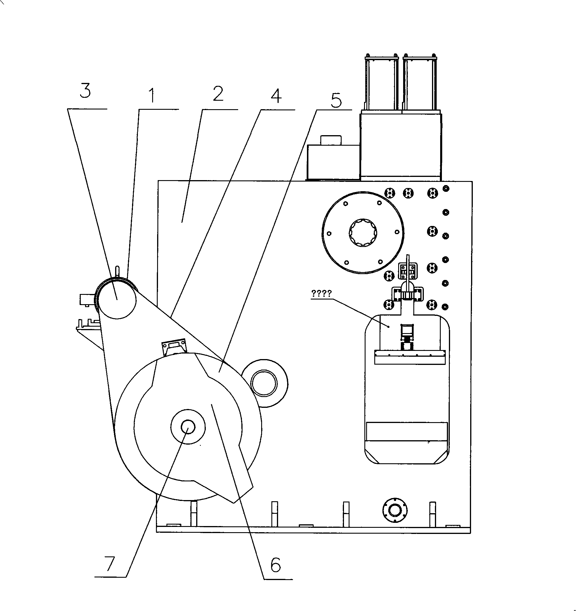
[0028] exist figure 1 Among them, a main motor (1) is installed on the bracket on one side of the frame (2) of the press as a power source. The driving force of the main motor (1) is transmitted to a flywheel (5) installed on the drive shaft (7) through a pulley (3) and a transmission belt (4), and a public The brake clutch (6) used is used to connect or disconnect the flywheel (5) from the drive shaft (7).

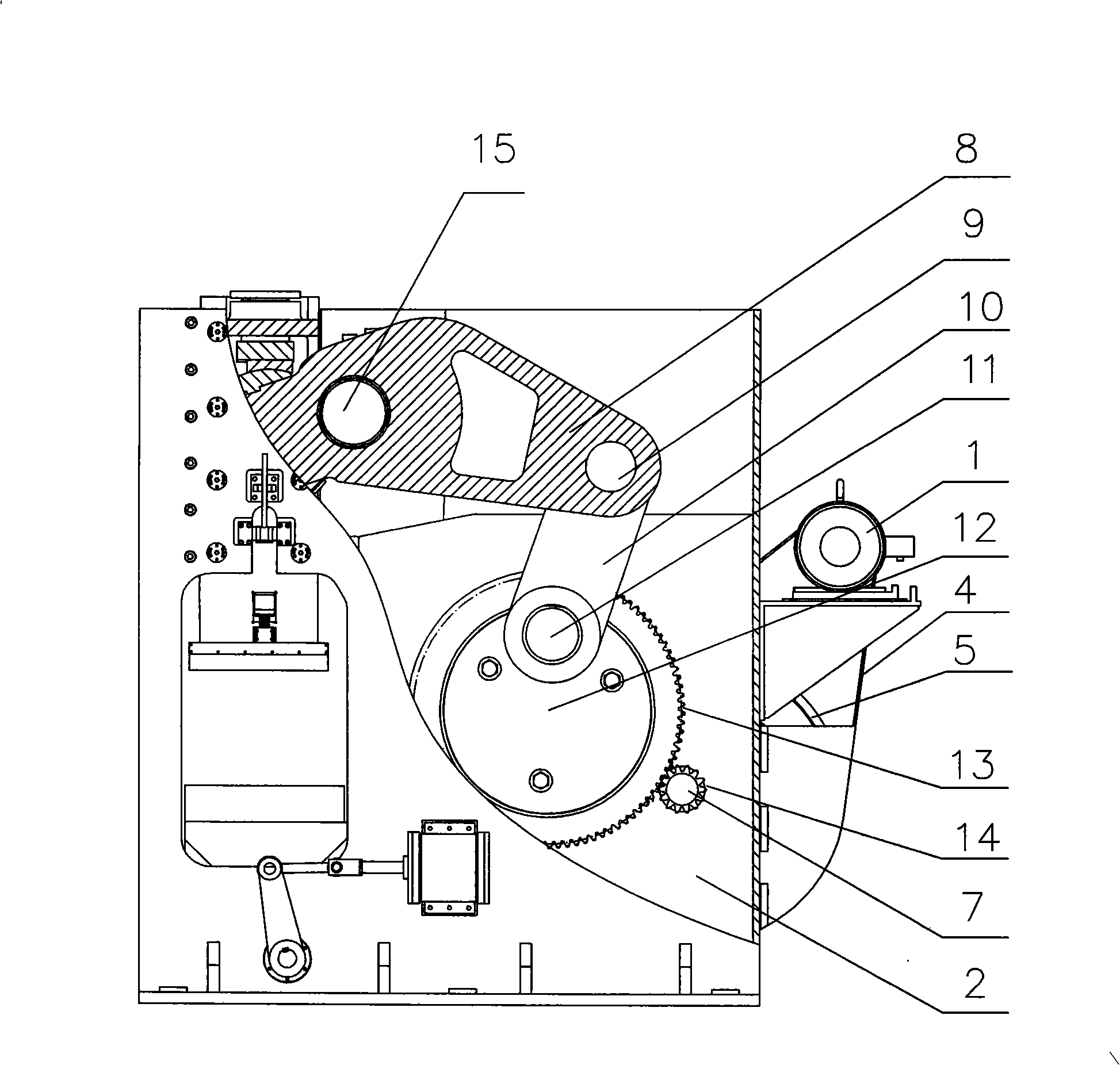
[0029] image 3 A schematic cross-sectional view of the drive structure of the press slider drive device of the present invention is given. Figure 4 A perspective view of the transmission structure of the drive device of the press of the present invention is given. exist image 3 , Figure 4 Among them, a base end of a transmission toggle lever (8) is rotatably connected to a drive link (10) by a connecting shaft (9), and the other end of the drive link (10) is rotatably mounted on a crankshaft ( 12) on the eccentric crank throw (11).

[0030] The crankshaft (12) is...


PUM


Abstract

The invention relates to a slide block driving device for multi-connecting-rod press machine. The slide block driving device comprises a frame, a motor, a fly wheel, a drive shaft, a transmission member, a slide block and a slide block lead rail. One end of the drive knuckle-lever of the transmission member is connected with and drives a connecting rod by a connection shaft and the other end of which is arranged on the side leg of a crank shaft. The coaxial deceleration gear of the crank shaft gears into a transmission gear arranged on the drive shaft. The slide block driving device is characterized in that the drive shaft is supported below one side of the frame by a bearing; the drive knuckle-lever is supported against the frame by the bearing in the manner of mismatched length; a drive tee is arranged at the other end; an upper fixed block and a lower fixed block are arranged in the drive chamber of the slide block; an upper rubbing block and a lower rubbing block are arranged between the drive tee and two fixed blocks respectively; the sphere of the drive tee is matched with two rubbing blocks and the drive tee can relatively slide between the running-in surfaces of two rubbing blocks; the upper fixed block is assembled by an adjustment bolt that is against the upper fixed block; and the lower fixed block is supported by a strut member that is against the lower fixed block. The slide block driving device has the advantages of stable running, small eccentric load and quick clearance adjustment, and thus is suitable for the such technologies as precise cold forging, cold warm forging, etc.

Description

technical field [0001] The invention relates to a press machine using a pressure head, in particular to a slider driving device of a multi-link press machine which uses a toggle mechanism to transmit pressure to the pressure head through a thrust member. Background technique [0002] At present, in the forging press publicly used in the forging industry, the slider drive device mostly adopts a crank slider mechanism, which converts the rotation of the power machine into the reciprocating motion of the slider through the rotation of the crankshaft. A flywheel is also used, and the slider is driven or stopped by engaging and braking the brake clutch to turn or stop the flywheel. For the forging press with this structure, the lifting speed curve of the slider is symmetrical with respect to the bottom dead center, that is to say, the falling speed and rising speed of the slider are the same. In the forging process of the workpiece, the slider is required to execute a very slow ...

Claims


Application Information

Patent Timeline
Patent Type & Authority Applications(China)
IPC IPC(8): B30B1/10B30B15/10B30B15/12
CPCB30B1/06
Inventor 邢立平
Owner SHANDONG JINCHEN MACHINERY CORP LTD LTD
Why Eureka
Try Eureka