
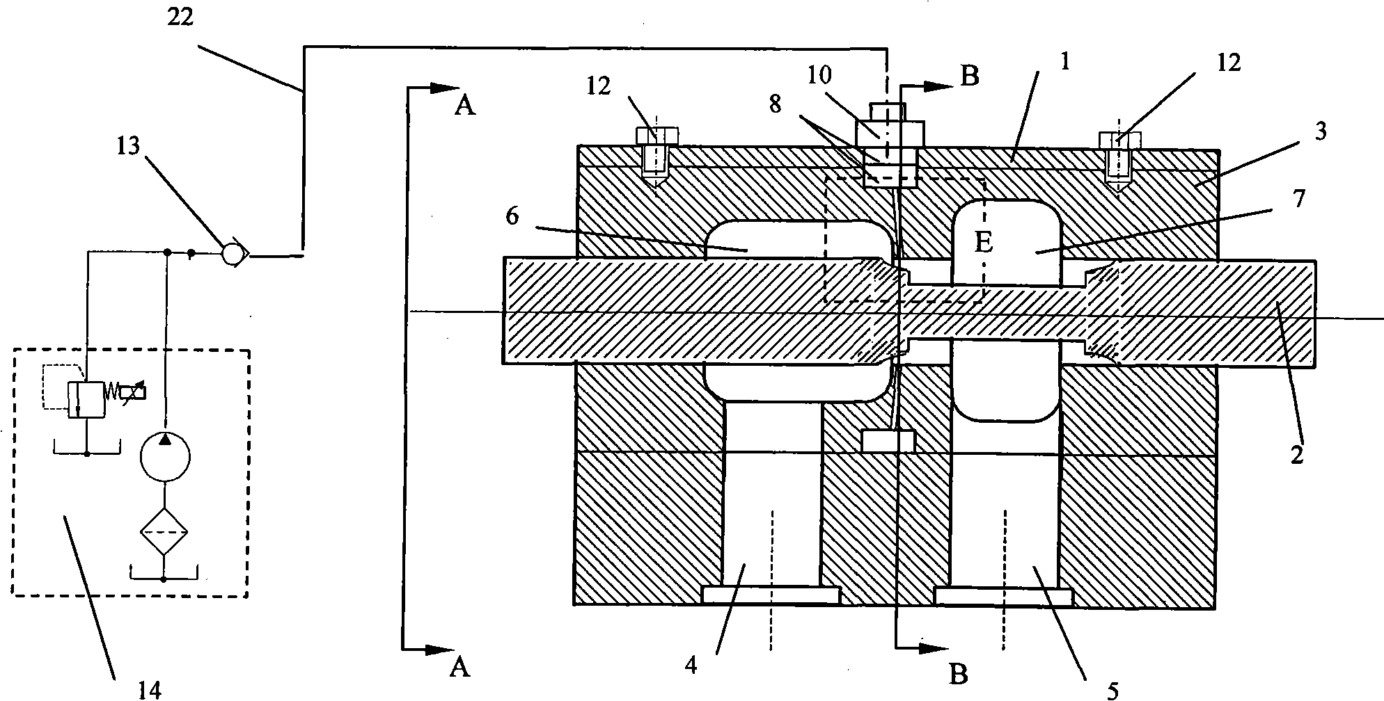
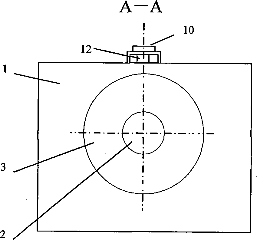
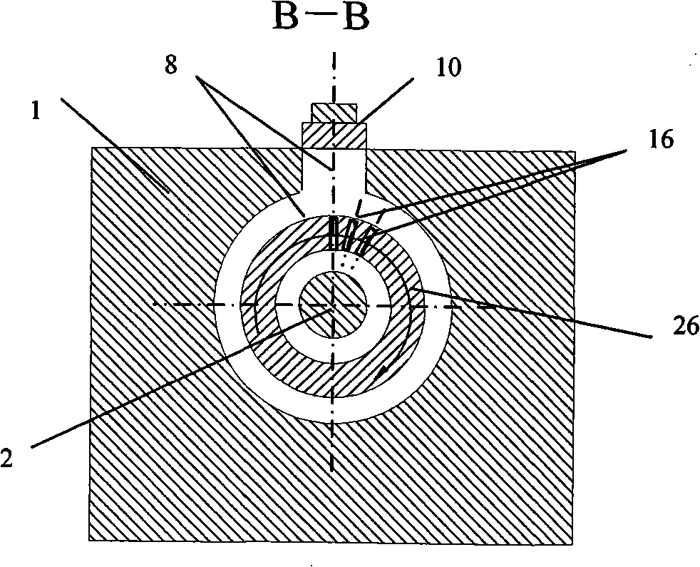
Pressure automatic filling type low noise throttling valve

A technology of automatic filling and throttling valve, applied in the direction of fluid pressure actuation device, lift valve, valve details, etc., can solve the problems of destroying flow and control characteristics, local pressure rise, poor suppression effect, etc., to improve noise Vibration and flow control characteristics, the effect of a single flow direction

Inactive Publication Date: 2008-12-17
ZHEJIANG UNIV
View PDF0 Cites 4 Cited by
  • Summary
  • Abstract
  • Description
  • Claims
  • Application Information

AI Technical Summary

Problems solved by technology

The development degree of cavitation changes with the change of pressure parameters. The general pressure injection method cannot well adapt to the characteristics of different development degrees of cavitation. If the pressure is insufficient, the suppression effect is not good. Has system flow and control features
Due to the limitation of research methods, it is not easy to obtain accurate and specific cavitation distribution
Improper pressure injection position, such as increasing the local pressure of the cavitation collapse area, although the cavitation will disappear quickly, it will cause greater cavitation noise

Method used


Image

  • Pressure automatic filling type low noise throttling valve
  • Pressure automatic filling type low noise throttling valve
  • Pressure automatic filling type low noise throttling valve

Examples


Embodiment Construction

[0027] The present invention will be further described below in conjunction with the accompanying drawings and embodiments.

[0028] Noise and vibration are common phenomena in hydraulic systems, which have great harm to the stability and reliability of the system and the life of components. The high-frequency noise generated by cavitation is a major environmental pollution. It is difficult to completely eliminate the problems caused by cavitation with respect to the current throttle valve structure. On the basis of ensuring the operating characteristics of the hydraulic system, it is an urgent problem to suppress the generation of cavitation as much as possible. According to the known principles of cavitation inception and cavitation sound, when the partial pressure of the liquid is lower than the air separation pressure or saturated vapor pressure, the gas will be separated from the liquid to form bubbles or bubble flow, that is, cavitation. The cavitation develops and coll...


PUM

PropertyMeasurementUnit
Axis angleaaaaaaaaaa
Diameteraaaaaaaaaa

Abstract

The invention discloses a pressure automatic filling type throttle valve with low noise. Cavitation is easy to occur in the throttling position when an ordinary throttle valve operates, and is attached to the wall surface of the ordinary throttling valve. In the pressure automatic filling type throttle valve, pressure filling holes are formed on the wall surface of the throttle valve of the invention and connected with an external oil source through a one-way valve; after cavitation occurs, filling power is generated between the local low pressure of the cavitation and the external oil source; oil liquid is filled into a cavitation space through the pressure filling holes, thereby effectively eliminating the cavitation, improving the local low pressure, and further inhibiting the reoccurrence of the cavitation. The throttle valve eliminates the noise, the vibration, the corrosion, etc. brought by the cavitation. The throttle valve has a structure of circumferential openings and non-circumferential openings and arc-shaped and step-shaped transitions are formed between a valve plug shaft and the throttling position of the valve plug. After the cavitation occurs, the pressure is extremely low, and forms the packing pressure with the external low pressure oil source; the packing pressure is self-adaptively filled in the cavitation space, thereby reducing the noise and the vibration of a throttling system and improving the flow control characteristics of the throttling system. The filled liquid oil has a single flow direction, and the low pressure oil source has high control precision, thus ensuring the original flow state of the system.

Description

technical field [0001] The invention relates to a throttle valve, in particular to a pressure automatic filling type low-noise throttle valve. Background technique [0002] Throttle valve is a basic form of hydraulic valve, used to control the movement speed and direction of the actuator, plus various operation control methods such as manual, proportional, electro-hydraulic servo, etc., its application is very wide. Structurally speaking, there are full-circle openings and non-full-circle openings. There are various forms of throttling structures, and their control characteristics have their own characteristics, but generally they have relatively narrow and complex flow channel structures, and the flow rate is high, and cavitation is unavoidable, which brings a lot of noise and vibration problems, and cavitation blocks the flow channel. Later, the system traffic will be saturated, making the system traffic uncontrollable. Weakening or eliminating air pockets is the key to ...

Claims


Application Information

Patent Timeline
IPC IPC(8): F16K47/02F16K27/02F16K1/34F15B13/02
Inventor 付新陆亮邹俊杜学文
Owner ZHEJIANG UNIV
Learn More