Hot pipe deposited horizontally

A technology of horizontal placement and heat pipes, applied in the field of heat pipes, can solve problems such as the decrease of the working efficiency of the heat pipes and the reduction of the effective heat exchange area of ​​the heat pipes.

Inactive Publication Date: 2008-12-17
XI AN JIAOTONG UNIV +1
View PDF0 Cites 12 Cited by
  • Summary
  • Abstract
  • Description
  • Claims
  • Application Information

AI Technical Summary

Problems solved by technology

Since the non-condensable gas needs to occupy a certain space in the tube, the effective heat exchange area of ​​the heat pipe is reduced, resulting in a decrease in the working efficiency of the heat pipe.

Method used


Image

  • Hot pipe deposited horizontally

Examples


Embodiment 1

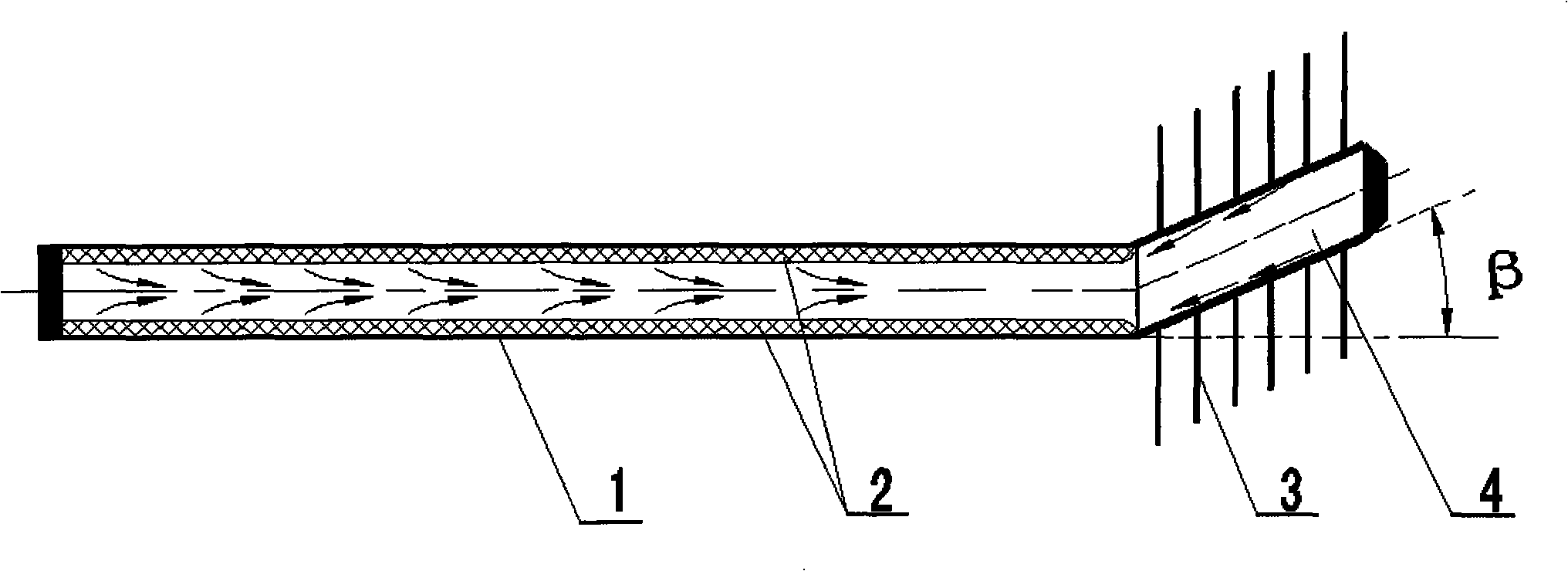
[0012] Embodiment 1: The heat pipe for horizontal placement includes a hollow pipe body with both ends closed and a working medium fluid 2 contained in the pipe body. In this embodiment, the material of the working medium is methanol. In addition, it can also be According to the use requirements of the heat pipe, materials such as ethanol, ethane, nitrogen or ammonia and other working fluid materials with phase change properties are used. The pipe body includes an evaporating section, an adiabatic section and a condensing section that communicate with each other. The adiabatic section is located between the evaporating section and the condensing section. The condensing section 4 forms an upward inclination angle β with respect to the evaporating and adiabatic section 1 . The outer circumference of the condensation section 4 is also provided with 1 to 20 annular cooling fins 3. The material of the cooling fins 3 is a metal sheet with good thermal conductivity. In this embodiment...

Embodiment 2

[0014] Embodiment 2: The upward inclination angle β of the condensation section is 5°-90°, which can be: 6°, 7°, 8°, 9°, 91°, 92°, 93°, 94° and other inclination angles. The mesh specification of the liquid-absorbing net is 100-145 mesh, which can be: 104 mesh, 144 mesh, etc. The wall thickness of the liquid-absorbing net is 0.10-0.45mm. Can be: 0.11mm, 0.12mm, 0.13mm, 0.14mm, 0.36mm, 0.37mm, 0.38mm, 0.39mm, etc. Among them, the angle of the inclination β, the mesh size of the liquid-absorbing net and the wall thickness of the liquid-absorbing net can all be matched with each other to form different combinations. Other structures of embodiment 2 are the same as embodiment 1.

Embodiment 3

[0015] Embodiment 3: The upward inclination angle β of the condensation section is 10° to 45°, which can be: 11°, 12°, 13°, 14°, 31°, 32°, 33°, 34°, 35°, 36°, 37°, 38°, 39°, 40°, 41°, 42°, 43°, 44° and other inclination angles. The mesh size of the liquid-absorbing net is 105-140 mesh, which can be: 108 mesh, 136 mesh, etc. The wall thickness of the liquid-absorbing net is 0.15-0.40mm. Can be: 0.16mm, 0.77mm, 0.18mm, 0.19mm, 0.36mm, 0.37mm, 0.38mm, 0.39mm, etc. Among them, the angle of the inclination β, the mesh size of the liquid-absorbing net and the wall thickness of the liquid-absorbing net can all be matched with each other to form different combinations. Other structures of embodiment 3 are the same as embodiment 1.


PUM


Abstract

A heat pipe for horizontal arrangement, which belongs to a heat transfer element, comprises a pipe body and a medium fluid in the pipe body, wherein the pipe body comprises an evaporation segment, a heat insulation segment and a condensation segment, which are communicated with each other; and heat-dissipating fins are arranged on the outer circumference of the condensation segment. The condensation segment of the heat pipe is inclined upwards by an angle beta relative to the evaporation segment and the heat insulation segment, and a liquid absorption net is arranged on the inner walls of the evaporation segment and the heat insulation segment of the pipe body. When the heat pipe works normally, the medium fluid is repeatedly circulated in the heat pipe to carry out rapid heat exchange. When the temperature of the condensation segment is higher than the temperature of the evaporation segment, the inclination angle of the condensation segment can allow the gas to gather at the condensation segment and the liquid to gather at the evaporation segment to prevent the occurrence of heat blockage due to the flowing and circulation of the medium in the pipe and prevent reverse heat transfer, so that the heat pipe can achieve one-way heat transfer function of one-way thermal diode by injecting only one medium. The heat pipe has the advantages of improved heat transfer efficiency, reduced processing steps and saved manufacture material.

Description

technical field [0001] The invention relates to a heat transfer element, and mainly relates to a heat pipe suitable for horizontal placement. Background technique [0002] As a high-efficiency and enhanced heat transfer element, the heat pipe uses the latent heat released by the working fluid during phase change to transfer heat. When one end of the heat pipe is heated, the working medium in the tube vaporizes and absorbs the heat of vaporization from the heat source. After vaporization, the steam flows to the other end and condenses when it encounters condensation, releasing latent heat to the heat dissipation area. The condensate generates backflow with the help of the capillary force of the inner wall material of the heat pipe, and continues to be heated and vaporized, so that the reciprocating cycle quickly transfers a large amount of heat from the heating area to the cooling area. In the working temperature range, its heat transfer capacity is about tens or even hundre...

Claims


Application Information

Patent Timeline
Patent Type & Authority Applications(China)
IPC IPC(8): F28D15/02
Inventor 吕彦力陶文铨石海军袁培薛牡丹
Owner XI AN JIAOTONG UNIV
Why Eureka
Try Eureka