Processor system, bus controlling method, and semiconductor device
A technology of processor system and virtual processor, which is applied in the direction of electrical digital data processing, instruments, computers, etc., can solve the problems of large performance estimation error, deterioration of CPU core performance, and affecting system performance, so as to achieve equalization and access performance effect
- Summary
- Abstract
- Description
- Claims
- Application Information
AI Technical Summary
Problems solved by technology
Method used
Image
Examples
Embodiment approach 1
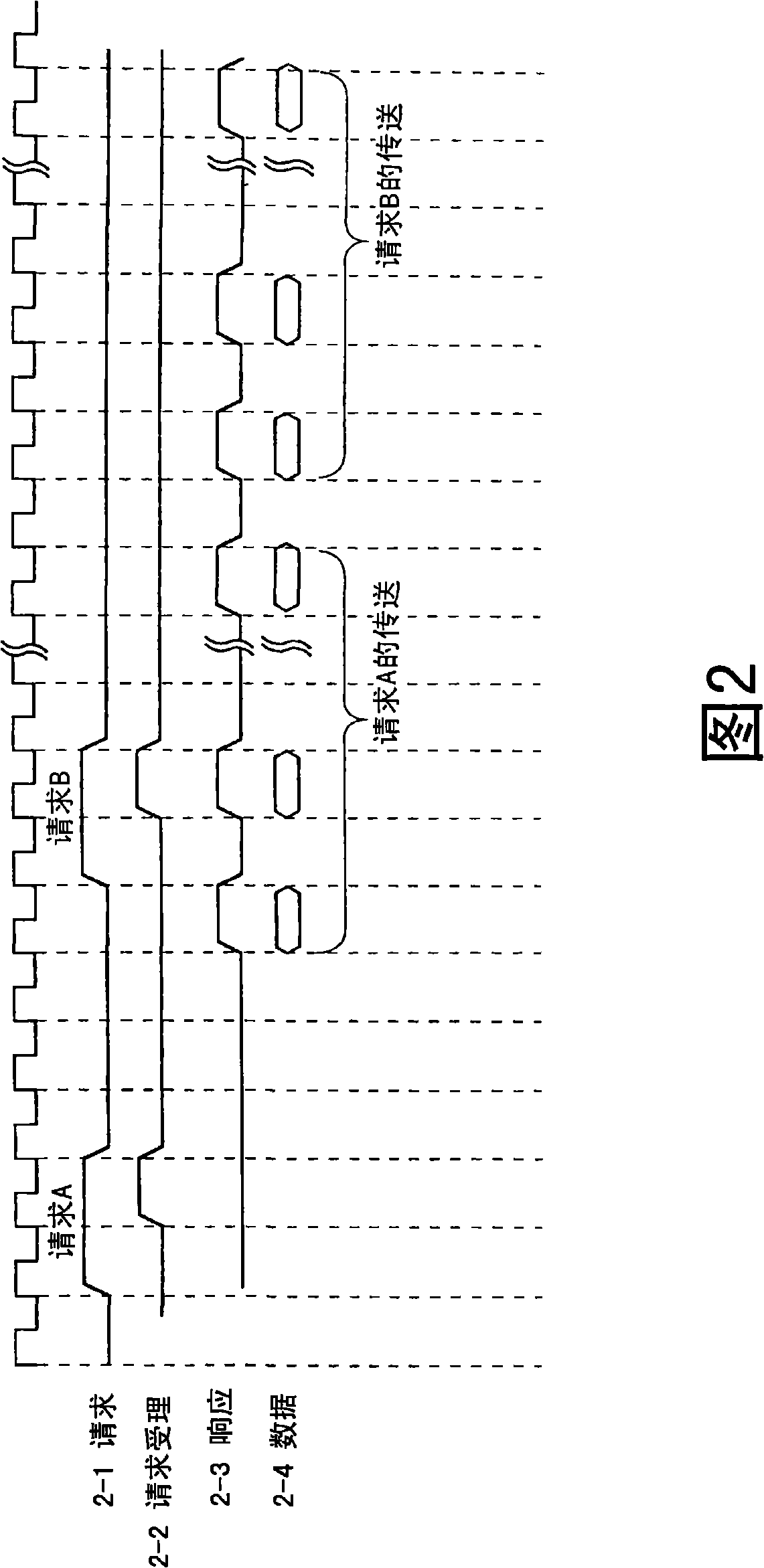
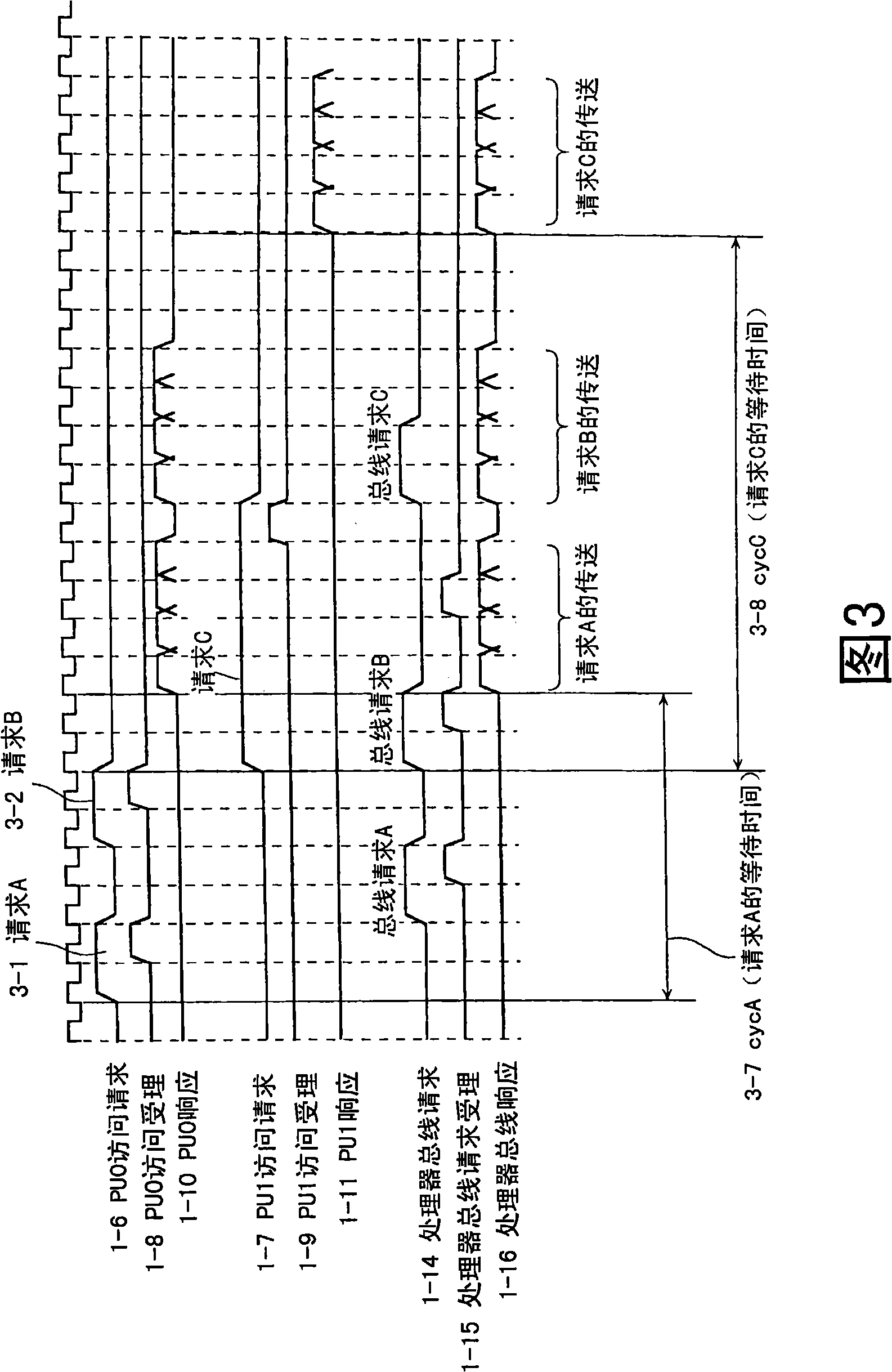
[0123] Embodiment 1 of the present invention will be described. The processor system in this embodiment is configured to limit the number of consecutive executions of the transfer phase corresponding to the plurality of access requests to the maximum when a plurality of access requests are continuously issued without leaving a predetermined period of time from one master unit. N times. Here, the "predetermined period" is a period corresponding to part or all of the period from when the access request issued immediately before is accepted to when the transfer phase of the access request is completed. Thereby, access performance among master units can be evenly distributed.
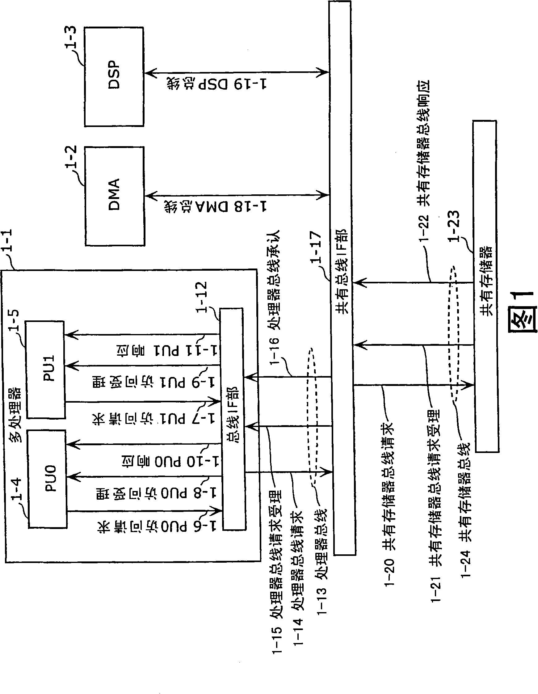
[0124] FIG. 4A is a configuration diagram showing a processor system in Embodiment 1 of the present invention. The processor system of FIG. 4A includes a multiprocessor 4-1 and a shared memory 4-24. In Embodiment 1, it is assumed that the multiprocessor 4-1 mounts two processor units (PU0, 1) as a plural...
Embodiment approach 2
[0179] Embodiment 2 of the present invention will be described. FIG. 7A is a system configuration diagram of Embodiment 2. FIG. In this embodiment, control is performed to allow continuous access from the same processor only for a certain set period. Parts that can be explained in the same way as in FIG. 4A are assigned the same symbols, and explanations thereof are omitted.
[0180] Compared with FIG. 4A, the bus IF part 4-10 of FIG. 7A increases the suppression cycle counter 7-1 which counts the predetermined number of cycles, and the suppression cycle setting register which can set and hold the predetermined number of cycles from any master unit. 7-4. The suppression cycle counter 7-1 is counted down after loading the cycle number set in the suppression cycle setting register 7-4, for example.
[0181] Each time an access request is accepted, the reception control unit 411 validates the flag information, sets identification information corresponding to the access request...
Embodiment approach 3
[0190] Embodiment 3 of the present invention will be described. FIG. 8A is a system configuration diagram of the third embodiment. In the present embodiment, control is performed to suppress a certain number or more of consecutive bus accesses from the same processor. The bus IF part 4-10 of Fig. 8A is compared with Fig. 4A, and the difference lies in increasing the continuous number permission register 8-5 that can set and keep the number of times N of continuous transmission from any master unit, and the continuous number of counts. Counter 8-1. The consecutive number counter 8-1 counts down after loading the N held in the consecutive number permission register 8-5, for example. Parts that can be explained in the same way as in FIG. 4A are assigned the same symbols, and explanations thereof are omitted.
[0191] Figure 8B It is a flowchart showing an example of the reception control processing in the reception control unit 412 . Figure 8B Compared with Fig. 4B, the di...
PUM
 Abstract
Description
Claims
Application Information
 - R&D
- Intellectual Property
- Life Sciences
- Materials
- Tech Scout
- Unparalleled Data Quality
- Higher Quality Content
- 60% Fewer Hallucinations
Browse by: Latest US Patents, China's latest patents, Technical Efficacy Thesaurus, Application Domain, Technology Topic, Popular Technical Reports.
© 2025 PatSnap. All rights reserved.Legal|Privacy policy|Modern Slavery Act Transparency Statement|Sitemap|About US| Contact US: help@patsnap.com


