Magnetic force driver

A transmission and magnetic technology, applied in the direction of electromechanical transmission, electric components, electrical components, etc., can solve the problems of inaccurate center sealing, vibration, etc., and achieve the effect of small volume, small motion inertia, simple and compact structure

Inactive Publication Date: 2008-12-17
DALIAN UNIV OF TECH
View PDF1 Cites 28 Cited by
  • Summary
  • Abstract
  • Description
  • Claims
  • Application Information

AI Technical Summary

Problems solved by technology

The magnetic drive adopts the radial structure of the torque from the outside to the inside, which effectively

Method used


Image

  • Magnetic force driver
  • Magnetic force driver
  • Magnetic force driver

Examples


specific Embodiment

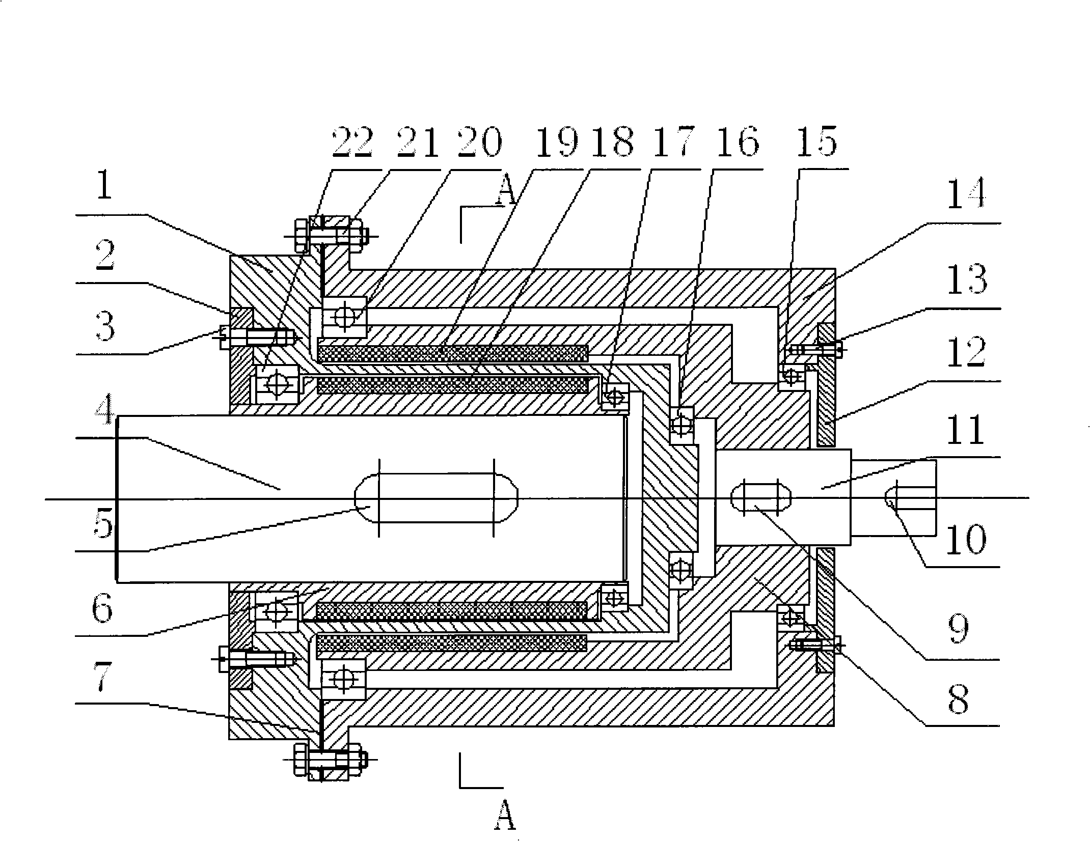
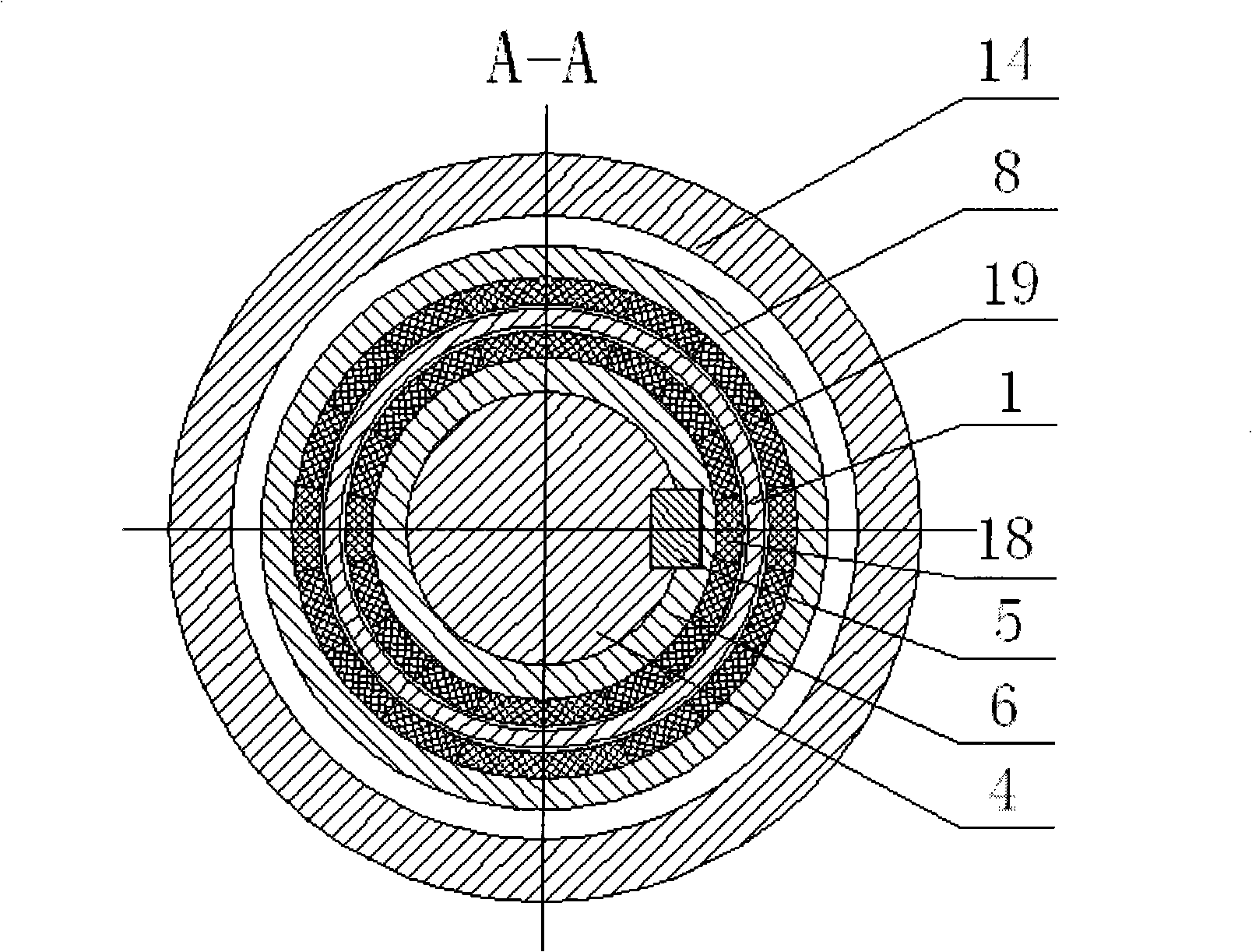
[0013] as attached figure 1 As shown, a magnetic actuator of the present invention includes four parts: a power input part, a power output part, a housing part and a magnetic circuit part. Under the support and positioning of the shell part, the original force is input through the power input part, the outer rotor 8 drives the outer permanent magnet 19 to rotate, the magnetic force line coupling of the magnetic circuit part drives the inner rotor 6 to rotate, and finally the obtained power is obtained through the power output part. Torque output to a vacuum environment. Here's how each movement works in detail:

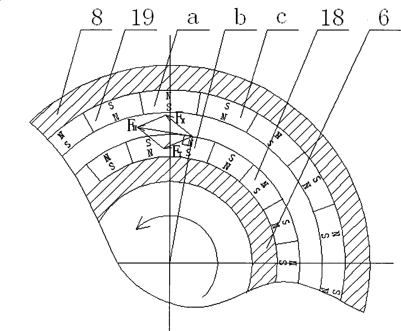
[0014] Start the motor, the torque output by the active motor is decelerated by the reduction gear to drive the input shaft 11 to rotate through the end key 10, the input shaft 11 drives the outer rotor 8 to start rotating through the connection of the key 9, and the outer permanent magnet 19 rotates synchronously thereupon. Take a pair of the first magnet a and the...


PUM


Abstract

The invention belongs to the technical field of the industrial robot, particularly to a magnetic driver used in the silicon slice transmission robot playing the silicon slice transmission and positioning action in the vacuum in the IC manufacturing industry. The magnetic driver comprises a drive input part for realizing the torque introduction, a drive output part for realizing the torque output, a case part and a magnetic circuit part; in the drive input part, the drive input part is connected with an input axis through an end bond, and the external rotor is connected with the input axis through the bond, and fixed with the case through a deep groove ball bearing. In the magnetic circuit part, the internal rotor and the internal permanent magnet, the external rotor and the external permanent magnet all adopt the glue joint. The magnetic driver of the invention has compact structure, tight magnet distribution, small volume, large transmission torque, easy control, stable operation, convenient dismounting, small sport inertia, applied in the vacuum robot with higher cleanness.

Description

technical field [0001] The invention belongs to the technical field of industrial robots, and in particular relates to a magnetic actuator for a silicon chip transmission robot that plays the role of silicon chip transmission and positioning in a vacuum environment in the IC manufacturing industry. Background technique [0002] In recent years, with the continuous development of science and technology and the information industry, higher requirements have been placed on the processing and manufacturing environment of silicon wafers, especially in the IC manufacturing industry, the improvement of technical indicators such as reliability, cleanliness and precision Has become the trend of industrial development. In order to meet this requirement, some foreign companies have developed vacuum robots for silicon wafer transfer, such as Brooks Company in the United States and Rorze Company in Japan. [0003] At present, vacuum robots generally use mechanical transmission. Mechani...

Claims


Application Information

Patent Timeline
IPC IPC(8): H02K51/00
Inventor 丛明李腾姜英杜宇
Owner DALIAN UNIV OF TECH
Why Eureka
Try Eureka