Plasma processing apparatus and radio frequency matching network thereof

A radio frequency matching and plasma technology, applied in the field of microelectronics, can solve the problems of small impedance matching range, less technological process, and difficulty in taking into account the volume cost of radio frequency matching network and the achievable range of impedance matching, so as to achieve a large impedance matching range, Small size and low cost effect

Inactive Publication Date: 2008-12-17
BEIJING NAURA MICROELECTRONICS EQUIP CO LTD
View PDF0 Cites 12 Cited by
  • Summary
  • Abstract
  • Description
  • Claims
  • Application Information

AI Technical Summary

Problems solved by technology

However, the realization of this technical effect is at the cost of sacrificing the adaptability of the plasma processing equipment. Since the impedance of the RF matching network itself can only change slightly with the RF frequency, the range of its impedance matching is relatively small, and it can only To meet the requirements of impedance matching in a small range, the plasma processing equipment can achieve fewer processes
[0012] Therefore, according to the current mainstream point of view, it is still difficult to balance the size and cost of the RF matching network with the achievable range of impedance matching.

Method used


Image

  • Plasma processing apparatus and radio frequency matching network thereof
  • Plasma processing apparatus and radio frequency matching network thereof
  • Plasma processing apparatus and radio frequency matching network thereof

Examples


Embodiment approach

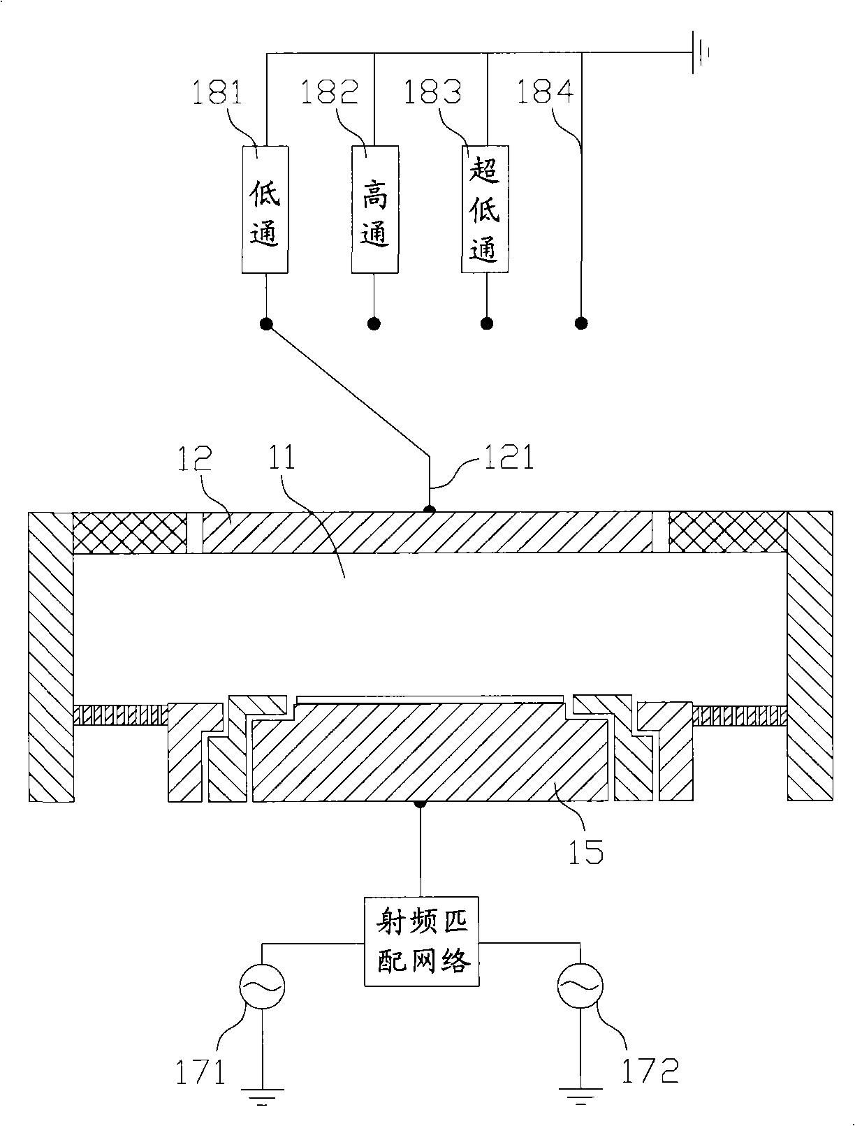
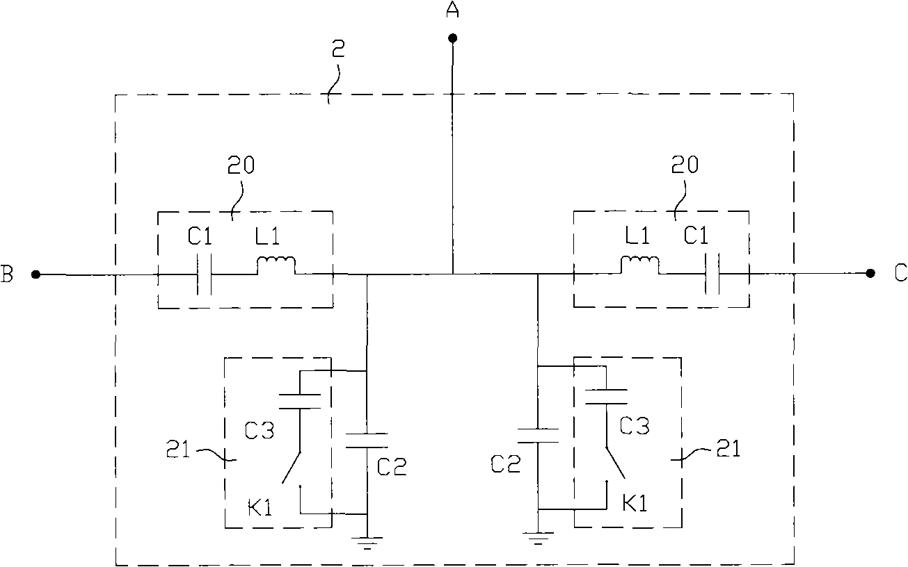
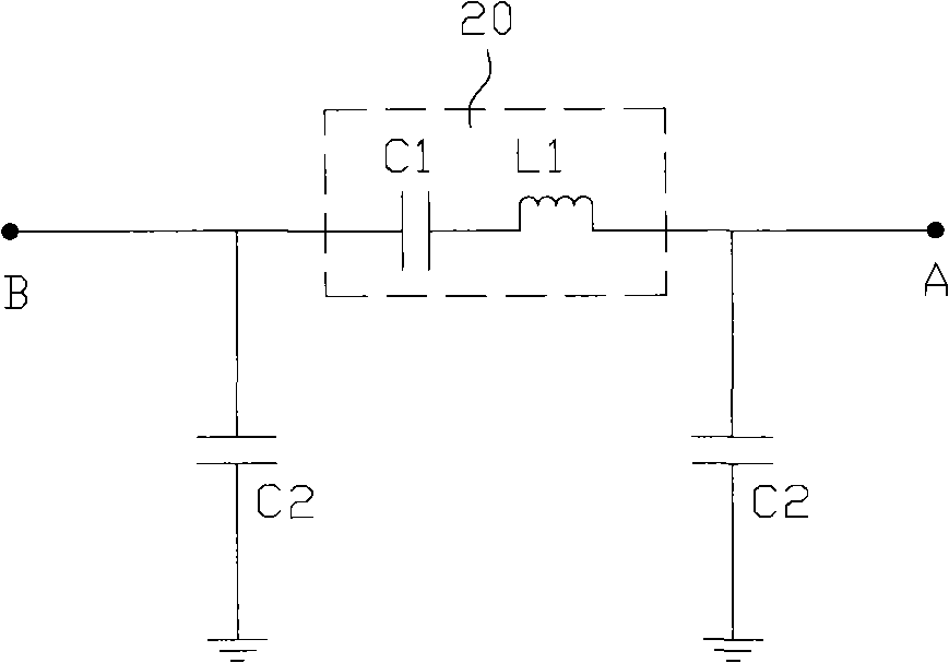
[0039] In the first specific implementation manner, the radio frequency matching network 2 provided by the embodiment of the present invention is arranged between the radio frequency driving electrodes and the radio frequency power supply.

[0040] The radio frequency matching network 2 includes a radio frequency output port A, and a radio frequency input port B and a radio frequency input port C; the radio frequency output port A is connected to the reaction chamber of the plasma processing equipment, and the radio frequency input port B and the radio frequency input port C are respectively connected to the first A radio frequency power supply and a second radio frequency power supply. The frequency of the first radio frequency power supply is relatively low, and its center frequency can be specifically 2MHZ. The frequency of the second radio frequency power supply is relatively high. Here, its center frequency can be specifically 60MHz. The frequencies of the two can usually ...


PUM


Abstract

The invention discloses a radio frequency matching network, comprising a radio frequency output port and at least two radio frequency input ports. A matching circuit between the radio frequency input ports and the radio frequency output port comprises a matching circuit which a first constant inductance and a first constant capacitor are connected in series to form. One end of the matching circuit is provided with a second grounded constant capacitor. The radio frequency matching network further comprises a first branch circuit. The first branch circuit comprises a first constant additional capacitor and a first switch which are connected with each other in series, and is connected with any of the first constant capacitor and the second constant capacitor in parallel. The invention also discloses plasma treatment equipment comprising the radio frequency matching network. Due to each element is all a constant element, the radio frequency matching network has small volume, low cost and faster matching speed, and at the same time, the impedance of the radio frequency matching network can be prominently changed by the first switch, and when the load impedance is greatly changed, the plasma treatment equipment still can favorably realize impedance matching.

Description

technical field [0001] The invention relates to the technical field of microelectronics, in particular to a radio frequency matching network for plasma processing equipment. The present invention also relates to a plasma processing device comprising the above-mentioned radio frequency matching network. Background technique [0002] Plasma processing equipment is a processing equipment widely used in the field of semiconductor manufacturing. There are great differences among different plasma processing equipments (the differences are usually manifested in the number of radio frequency power sources, specific structural forms, etc.), and the following only takes one of them as an example to briefly introduce it. [0003] Please refer to figure 1 , figure 1 It is a schematic structural diagram of a typical plasma processing equipment in the prior art. [0004] A plasma processing device generally includes a casing (no reference numerals are added in the figure), in which a ...

Claims


Application Information

Patent Timeline
Patent Type & Authority Applications(China)
IPC IPC(8): H05H1/46H01L21/00H01J37/32
Inventor 南建辉宋巧丽
Owner BEIJING NAURA MICROELECTRONICS EQUIP CO LTD
Why Eureka
Try Eureka